The article discusses the roles of multiplexer and demultiplexer in data communication systems, explaining how they function oppositely to manage the flow of data between multiple sources and destinations. It also illustrates their practical application in sharing a decoder among multiple seven-segment displays using a simplified circuit example.
Multiplexer and demultiplexer are two devices very important in data communications. As the name implies, their functions are opposite to each other (similar to encoder and decoder). These devices are used for sharing a device between two or more applications.
Consider, for instance, a decoder for seven-segment display. If we have a four-digit decimal number to display then we need four seven-segment displays and each one requires a decoder. However, by using a multiplexer and a demultiplexer, one unit of a decoder can be shared between the four displays.
Multiplexer
The role of a multiplexer is to receive the information from different senders and deliver it to its output. By receiving a select data, a multiplexer is instructed from which sender to receive data.
We may say, a single multiplexer (we may have multiple units of multiplexer) at a time selects information from one of many input lines and directs it to a single output. The select data then can successively address other inputs. N select lines can address 2N data input lines as senders of information.
Demultiplexer
The role of the demultiplexer is to receive information from one line input and deliver it to one of many output lines or devices as specified by the select data, which is also received by the demultiplexer. By receiving a select signal demultiplexer channels the main data to a particular address.
In other words, a simple demultiplexer receives one channel of input data and directs it to one of the many output channels, as selected by the select data. Depending on the select data bit size a maximum of 2, 4, 8, 16, 32, and so forth can share the main data.
Figure 1 shows the schematic of a pair of multiplexer/demultiplexer for transferring data over a single line.
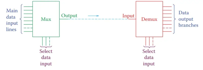
Figure 1 Schematic of a multiplexer and a demultiplexer.
In the arrangement in Figure 1, if the select data in the multiplexer have a pattern based on which the data lines are continuously selected in an orderly manner, the same pattern can be given to the demultiplexer, and consequently, after synchronization, all data are sent and received over the line between the two. This is what happens in communication devices.
Figure 2 illustrates a very simplified circuit for the example of the driver for a seven-segment display.
- The multiplexer in this example directs a set of four incoming data to its output, which goes to the decoder (driver).
- After decoding is done, the information for a to g segments are put on a data bus (a bus is the main line in an electric or electronic device that provides voltage or data to all components) that is shared between the four display units. Only one of the units will light up at a time because the select data are also sent to the demultiplexer, based on which only one of the display units is connected to the positive voltage.
- In here it is assumed that the display segments have a common anode that needs to be connected to the positive terminal. In general, the LED’s in a seven-segment display can be connected in two ways. They have either a common anode or a common cathode. Their other sides are then connected to the driver data bus.
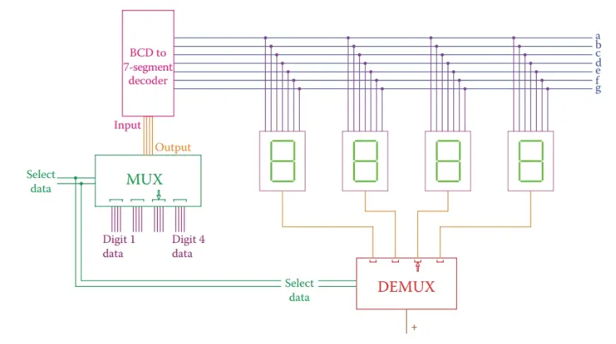
Figure 2 Simplified circuit showing multiplexer and demultiplexer for seven-segment display units sharing a driver.
Multiplexer and Demultiplexer Key Takeaways
Multiplexer and Demultiplexer plays a vital role in optimizing data communication and hardware resource utilization. Their ability to efficiently control and route data between multiple sources and destinations makes them essential in various applications, such as digital displays, communication systems, and microprocessor-based devices, where minimizing hardware components while maintaining functionality is crucial.