This article covers the Medium Voltage Circuit Breakers Construction, Four Major Components, and Operating/Working Mechanism/Principle in detail along with labeled circuits diagrams.
Low- and medium-voltage Vacuum circuit breakers are similar in construction and operation. One of the primary differences between them is that the OCPDs on LVPCBs are mounted on the circuit breakers, while medium-voltage circuit breakers use protective relays, which are typically mounted on the enclosure door.
Medium-voltage circuit breakers have the following four major components:
- Disconnects (stabs) main stabs secondary stabs ground stabs
- Contact assemblies arcing contacts main contacts auxiliary mechanism-operated contacts (MOCs) truck-operated contacts (TOCs)
- Arc extinguishers (arc chutes)
- Operating mechanisms (frames)
Vacuum circuit breakers do not use arcing contacts. Also, instead of large, heavy contact assemblies and arc chutes, they use vacuum bottles with smaller contacts to extinguish arcs.

Overcurrent Protective Devices on Medium Voltage Circuit Breaker
- Main Disconnects
Most medium-voltage metal-clad circuit breakers have tulip-style (round) disconnects with springs around them to ensure good contact with the bus. However, certain OEMs sometimes place bus type, straight finger connections on small-frame circuit breakers.
The main disconnects are mounted on the bushings, or pole units. Bushings are constructed of copper alloy, connect the primary disconnects to the stationary contact assembly, and are covered with insulation. Epoxy-coated paper, which can absorb moisture over time, is used as insulation for many medium-voltage air circuit breakers. Some manufacturers use porcelain. See Figure 1.

Figure 1. Medium Voltage Circuit Breaker Primary Disconnects
- Secondary Disconnects
Secondary disconnects are often mounted on the contact block located on the lower right-hand corner of medium-voltage metal-clad circuit breakers (when facing the rear of the circuit breaker). Vertical lift circuit breakers, such as the GE MagneBlast, are an exception to this typical design. The secondary contact block of vertical lift circuit breakers is mounted on the top of the circuit breaker on the right-front corner (when facing the front of the circuit breaker).
Many horizontal racking circuit breakers have a T-handle extension that must be operated in order to make the secondary disconnects and place the circuit breaker into the test position.
Unlike LVPCBs, medium-voltage metal-clad circuit breakers usually do not have a separate test position. They are racked to the disconnected position, and the secondary disconnect is extended until it makes contact with the stationary secondary disconnects located in the rear of the cubicle. See Figure 2.

Figure 2. Medium Voltage Circuit Breaker Secondary Disconnects
- Medium-Voltage Circuit Breaker Contact Assemblies
The function of the main and arcing contacts is the same in medium-voltage air and vacuum circuit breakers as in LVPCBs. Instead of zinc being used to harden the arcing contacts, tungsten is often used for medium-voltage air circuit breakers. The arc runners in the arc chute are connected to the line and load sides of the circuit breaker, respectively. This means that when the arc chute is installed on a medium-voltage circuit breaker, both it and the arc runners are energized. See Figure 3.

Figure 3. Medium Voltage Circuit Breaker Contact Assemblies
- Auxiliary Contact Assemblies
The auxiliary contacts of medium-voltage metal-clad switchgear are typically mounted on the switchgear rather than the circuit breaker frame. They are known as a mechanism-operated contact (MOC) and truck-operated contact (TOC) switches. MOCs are mechanically driven from the operating mechanism and are used for control and indicating circuits. See Figure 4. The TOC switch is used to disable the circuit breaker during racking operations. It is operated when the circuit breaker is racked in or out of its cell.
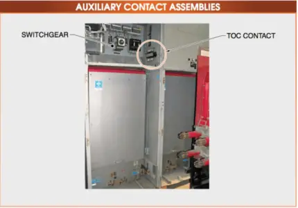
Figure 4. Medium Voltage Circuit Breaker Auxiliary Contact Assemblies
- Arc Chutes
Another area in which low- and medium-voltage air circuit breakers are similar is the arc interruption process. The basic construction of low- and medium- voltage arc chutes is similar. However, the arc in a medium-voltage circuit breaker is more persistent, which means it is harder to extinguish. Medium- voltage circuit breakers add several aids, such as puffers, blowout coils, and pole pieces, to ensure that arcs are extinguished quickly and effectively.
Operating Mechanism of Medium-Voltage Circuit Breakers
Modern operating mechanisms are quick to make, quick break. This means that the speed of operation is independent of the speed of the control handle. The modern circuit breaker operating mechanisms are said to be stored energy mechanisms since there are both opening springs and closing springs. One set of springs usually has tension on it. For this reason, extreme care should be taken when working on or near circuit breaker contacts. They have heavy moving contact assemblies and powerful springs.
If a technician were to place his hand between the moving and stationary contacts when it closed, he could be maimed. Even when opening, these devices have such force that they could break bones. Plenty of clearance should be allowed between any body part and the moving parts of a circuit breaker. Closing springs accelerate the contacts to the closed position but do not hold the contacts closed. If only the closing springs were relied upon to keep contacts closed, over a period of time the springs would weaken, causing the contacts to bounce, vibrate, and burn.
GE Power/Vac® ML-18 Medium Voltage Circuit Breaker Operation
The contacts are held in a closed position by a prop-and-roller operating mechanism. The prop and roller put the contact linkage into a mechanical bind, forcing the contacts to stay tightly closed. LVPCBs and medium-voltage vacuum circuit breakers (such as the GE Power/Vac® ML-18) have advanced prop-and-roller operating mechanisms. See Figure 5. In Figure A, the closing springs are discharged and the circuit breaker is open.

Figure 5. GE Power/Vac® ML-18 Medium Voltage Circuit Breaker Operating/Working Mechanism/Principle
The closing toggles (7A and 7B) and the trip link (6) are collapsed, which allow the bellcrank (1) to rotate counterclockwise. This rotation forces the pushrod connected to the bell crank down, opening the contacts in the vacuum bottle. A bell crank (bell crank lever) is used to change from one direction to another, usually at a 90° angle. It is almost always triangular in shape and is connected to a pivot pin on one end. The closing springs force the contacts closed, so the bell crank is forced to rotate. When electrical control power is applied to the circuit breaker, as in 5 (Figure B), the closing springs charge and the trip latch (3) drops against the trip roller (4). This forces the other closing toggle (7a) down also and into the crook of the prop (8). The trip link (6) also drops to a near-horizontal position.
This sequence prepares the circuit breaker to close its contacts when the close button is pressed. Pushing the close button discharges the closing springs, which forces the closing cam to rotate counterclockwise, as in 5 (Figure C). When it does, both closing toggles and the trip link are pushed upward, and the bellcrank (1) rotates clockwise. The pushrod, connected to the vacuum bottle contacts, is forced upward, which closes the contacts. The contacts are now held in the closed position by the prop’s interference with the closing roller (5). As long as the prop is in this position, the circuit breaker will stay closed. A line through the centre of the roller and pivot diagram illustrates the entire mechanical force of the mechanism concentrated through these points in 5 (Figure D).
To trip the circuit breaker, the trip latch (3) is rotated counter-clockwise, which releases the closing toggles and the trip link. The bell crank is forced counterclockwise, and the contacts open.
Usually, the closing springs recharge when the circuit breaker closes. Some manufacturers set up the sequence so that they must recharge the springs when the circuit breaker is tripped. Reviewing the internal schematic and how the various limit switches and interlocks are sequenced will indicate how the circuit breaker will operate.
Westinghouse/Cutler- Hammer DS 480 V Medium Voltage Circuit Breaker Operation
Another example of a prop-and-roller mechanism is the Westinghouse/Cutler- Hammer DS 480 V circuit breaker operating mechanism. This is the same basic design that is used on their medium-voltage vacuum circuit breakers. The mechanism is shown with the contacts open and the springs discharged. Note the position of the main link (prop) as well as the closing cam. See Figure 6 (Figure A).
When the circuit breaker is inserted into the cubicle, the springs charge, which causes the closing cam to rotate approximately 90° (as shown in Figure B). The roller constraining link is rotated by the closing cam, which allows the trip latch to drop under the trip shaft. The edge of the trip latch is caught under the tip of the trip bar and held in place. The mechanism is held in the ready-to-close position by the closing springs applying force to the closing cam, which is prevented from rotating by the spring release latch.
When the close button is activated, the closing coil energizes, and the spring release latch allows the closing cam to rotate. (As shown in Figure C). As the contacts close, the springs discharge, and the main link is forced up by the closing cam rotation, which forces the contacts closed. All the force of the opening springs is now being applied to the centerline of the pivots of the bell crank, main link, and closing cam, causing the contacts to be mechanically held closed.
To trip the circuit breaker into the contact open position, the trip button is depressed, which rotates the trip shaft, allowing the trip latch to release. Since the roller constraining link is no longer being held by the trip shaft, the opening springs force the closing cam to rotate, allowing the contacts to open.

Figure 6. Westinghouse/Cutler- Hammer DS Medium Voltage Circuit Breaker Operating/Working Mechanism/Principle
ABB/ITE K-Line 600 V Medium Voltage Circuit Breaker Operation
A common type of LVPCB is the ABB/ITE K-Line 600 V circuit breaker. With this type of circuit breaker, the small bearing in the main roller (arrow) often seizes due to dirt or corrosion. This causes a trip-free condition or prevents the circuit breaker from tripping when the trip button is depressed. See Figure 7.

Figure 7. ABB/ITE K-600 Medium Voltage Circuit Breaker Operating/Working Mechanism/Principle
-
Frames
The frame on a medium-voltage air or vacuum circuit breaker has the same function as the frame on an LVPCB. It supports the contact assemblies or vacuum bottles and the primary disconnects. The frame on medium-voltage air and vacuum circuit breakers is heavier due to the increased weight and spacing of the components. See Figure 8.
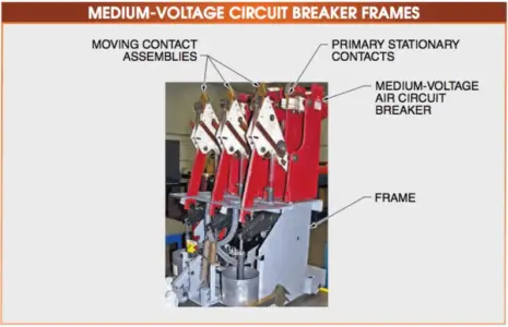
Figure 8. The frame on a medium-voltage circuit breaker
- Vacuum Circuit Breakers
Vacuum circuit breakers share the same basic operating mechanism and other components as air circuit breakers, except that vacuum bottles, are used in place of arc chute and contact assemblies.
The primary advantage of vacuum circuit breakers is their size. A vacuum circuit breaker is about half the size of a medium-voltage air magnetic circuit breaker. This means that there can be two per section of switchgear instead of just one. Vacuum bottles also require little maintenance compared to air magnetic contact and arc chute assemblies. The contact moves only about 1/2′′ in the vacuum bottle, and the opening springs are considerably lighter than the opening springs in an air-magnetic circuit breaker. This reduces wear on the assembly as well as their size and weight since the use of heavy metal supports and a heavy frame can be reduced. See Figure 9.

Figure 9. Vacuum circuit breakers have the same basic operating mechanisms as air circuit breakers.
Since the vacuum cannot be checked once the bottle is in service, it must be tested using an alternating current (AC) high-potential test set, or hipot tester, or a MAC tester.
A hipot tester is a test instrument that measures insulation resistance by measuring leakage current. A magnetron atmospheric condition (MAC) tester measures the internal pressure of a vacuum bottle and helps determine the remaining life of a vacuum bottle. A vacuum bottle is most likely to fail when the circuit breaker is closed after being opened.
The vacuum bottle does not usually fail during the opening since the load is removed from all three phases at the same time. However, when it is closed, especially when there is a large inrush of current or a fault, the bottle could fail violently. Most often it will not cause much damage, but there is a chance of personal injury.

Vacuum Circuit Breaker Failure Diagram
Medium Voltage Circuit Breakers Operation Key Takeaways
Understanding the construction, components, and operating mechanisms of medium-voltage circuit breakers is crucial for ensuring safe and reliable power distribution in industrial and commercial settings. Each element—from the disconnects and contact assemblies to the arc extinguishers and operating mechanisms—plays a vital role in interrupting fault currents, protecting equipment, and maintaining power system stability. These circuit breakers are widely used in substations, power plants, and large-scale facilities where consistent voltage regulation and quick response to electrical faults are essential. By employing advanced features like vacuum bottles, prop-and-roller mechanisms, and spring-loaded operations, medium-voltage circuit breakers not only enhance operational efficiency but also reduce maintenance needs and downtime.