This article covers the major distribution substation components, including protection, isolation, surge protection, conductors, and voltage regulation. It explains their roles in maintaining safe, reliable, and stable power distribution.
Substations are very important parts of the electrical power systems. The link between the high-voltage transmission lines and the low-voltage power distribution systems is the substation. The function of a distribution substation, such as the one shown in Figure 1, is to receive electrical power from a high-voltage system and convert it to voltage levels suitable for industrial, commercial, or residential use. The major functional components of a substation include:
- Transformers
- Fuses
- Circuit Breakers
- Disconnect Switches
- Lighting Arresters
- Insulators
- Conductors
- Voltage Regulators
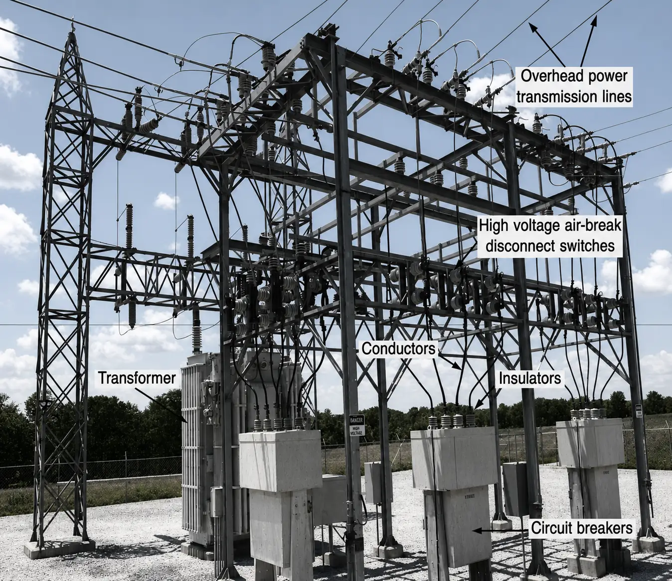
Figure 1. An outdoor substation showing the construction of high-voltage circuit breakers and disconnect switches
Distribution Transformers
Distribution transformers are the final voltage transformation stage in a power distribution system, reducing medium-voltage feeder levels to utilization voltages for residential, commercial, and small industrial loads. Common distribution ratings include 11 kV, 13.8 kV, and 33 kV on the primary side, with secondary voltages such as 400/230 V or 480/277 V. They are typically installed as pole-mounted, pad-mounted, or substation units and are selected based on connected load, expected demand, voltage requirements, and future load growth.
Transformer connections also affect distribution-system performance. Delta–wye transformers are widely used because the grounded-wye secondary provides a neutral for single-phase loads and a path for zero-sequence currents, while the delta winding helps contain triplen harmonic currents. Distribution transformers may also use fixed taps to accommodate feeder-voltage variations, and their impedance influences voltage drop and available fault current at the secondary terminals.
Because distribution transformers remain energized continuously, losses are an important consideration in system planning and operation. Core losses occur whenever the transformer is energized, while winding losses increase with load current; therefore, transformer sizing should consider both peak demand and expected loading over time. Proper selection helps maintain acceptable secondary voltage, limit losses, withstand available fault levels, and provide reliable service to connected distribution loads.
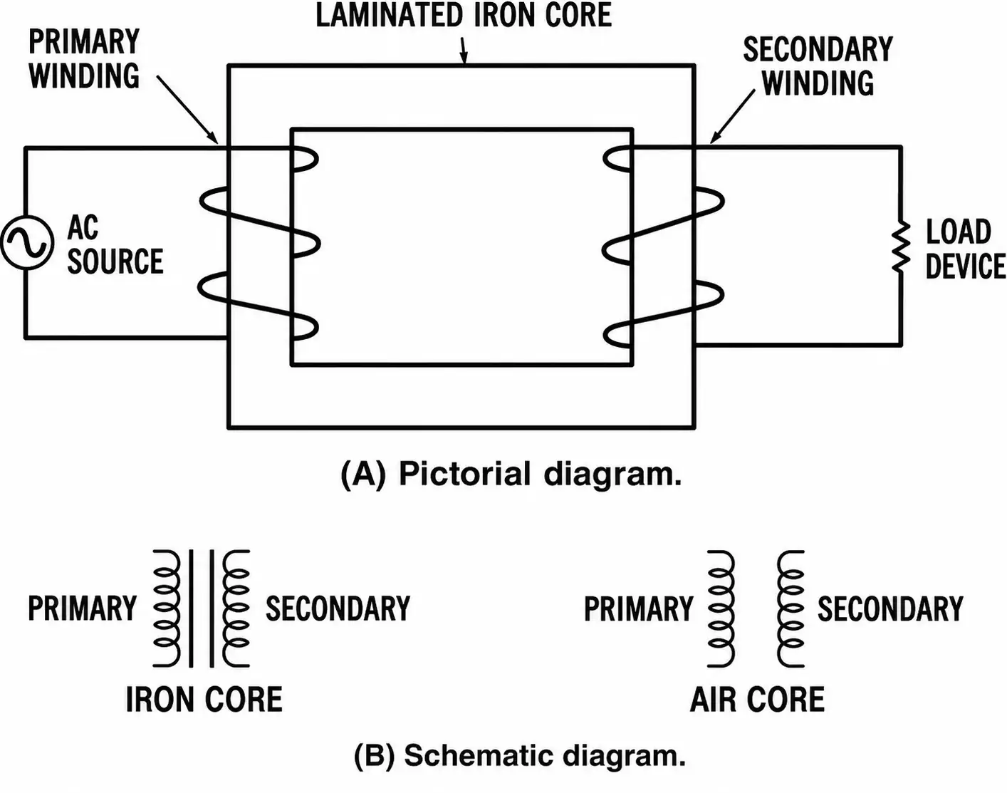
Figure 2. Basic transformer construction: (A) pictorial design; (B) schematic diagram.
High-Voltage Fuses
Since power lines are frequently short circuited, various protective equipment is used to prevent damage to both the power lines and the equipment. This protective equipment must be designed to handle high voltages and currents. Either fuses or circuit breakers may be used to protect high-voltage power lines.
High-voltage fuses (those used for over 600 volts) are made in several ways.
- An expulsion-type fuse has an element that will melt and vaporize when it is overloaded, causing the power line it is connected in series with to open.
- Liquid fuses have a liquid-filled metal enclosure that contains the fuse element. The liquid acts as an arc-suppressing medium. When the fuse element melts from an excessive current in a power line, the element is immersed in the liquid to extinguish the arc. This type of fuse reduces the problem of high-voltage arcing.
- A solid-material fuse is similar to a liquid fuse, except that the arc is extinguished in a chamber filled with solid material.
Ordinarily, high-voltage fuses at substations are mounted adjacent to air-break disconnect switches. These switches provide a means of switching power lines and disconnecting them for repair. The fuse and switch enclosure is usually mounted near the overhead power lines at a substation.
High-Voltage Circuit Breakers
Circuit breakers that control high voltages are also located at electrical substations (see Figure 3). In this type of circuit breaker, the contacts are immersed in an insulating oil contained in a metal enclosure.
Another type of high-voltage circuit breaker is the magnetic air breaker in which the contacts separate, in the air, when the power line is overloaded. Magnetic blowout coils are used to develop a magnetic field that causes the arc (which is produced when the contacts break) to be concentrated into arc chutes where it is extinguished.
A modification of this type of circuit breaker is the compressed-air circuit breaker. In this case, a stream of compressed air is concentrated on the contacts when the power line is opened. The compressed air aids in extinguishing the arc that is developed when the contacts open. It should be pointed out that large arcs are present whenever a high-voltage circuit is interrupted. This problem is not encountered to any great extent in low-voltage protective equipment.
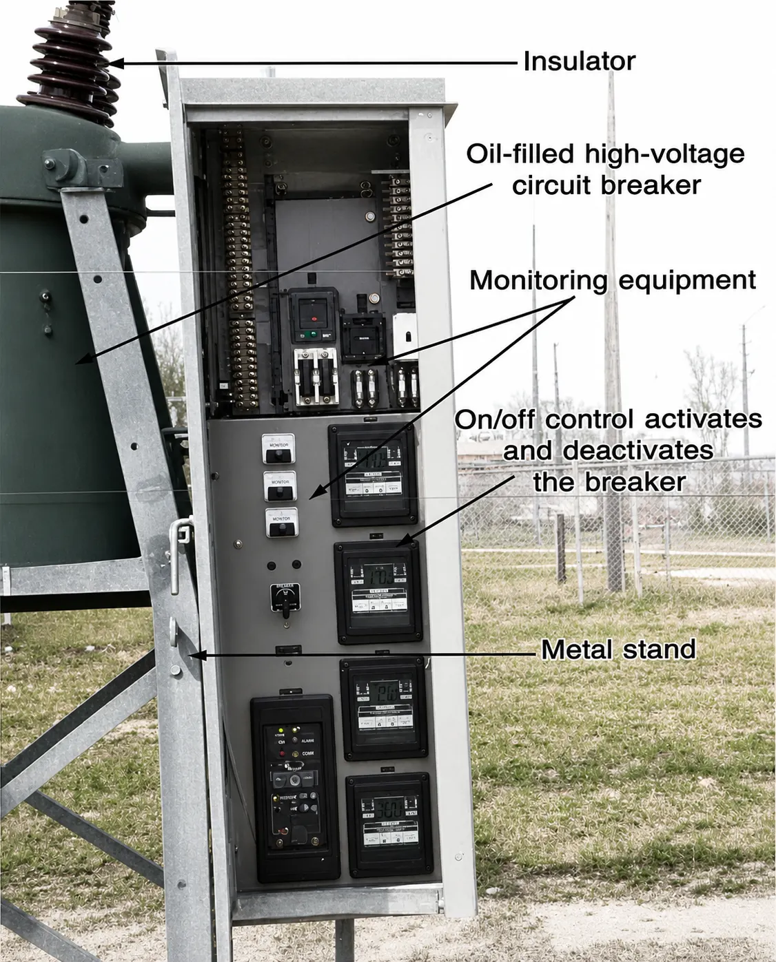
Figure 3. Circuit breakers and other equipment used at a substation.
There are two major types of high-voltage circuit breakers—oil-filled and oil-less. These circuit breakers are designed to operate on voltages of 1000 volts to over 500,000 volts. Oil-filled circuit breakers are used primarily for outdoor substations, except for very high voltages in the range of 500,000 volts and higher. Oil-less circuit breakers are ordinarily used for indoor operation.
High-Voltage Disconnect Switches
High-voltage disconnect switches are used to disconnect electrical equipment from the power lines that supply the equipment. Ordinarily, disconnect switches are not operated when current is flowing through them. A high-voltage arcing problem would occur if disconnect switches were opened while current was flowing through them. They are opened mainly to isolate equipment from power lines for safety purposes.
Most disconnect switches are the “air-break” type, which is similar in construction to knife switches. These switches are available for indoor or outdoor use in both manual and motor-operated designs.
Lightning Arresters
The purpose of using lightning arresters on power lines is to cause the conduction to ground of excessively high voltages that are caused by lightning strikes or other system problems. Without lightning arresters, power lines and associated equipment could become inoperable when struck by lightning.
Arresters are designed to operate rapidly and repeatedly, if necessary. Their response time must be more rapid than that of the other protective equipment used on power lines.
Lightning arresters (see Figure 4) must have a rigid connection to ground on one side. The other side of the arrester is connected to a power line. Sometimes, they are connected to transformers or the insides of switchgear. Lightning is a major cause of power system failures and equipment damage; so lightning arresters have a very important function. Lightning arresters are also used at outdoor substations.
The lightning arrester is used to provide a path to ground for lightning strikes or hits. This path eliminates the flashover between power lines, which causes short circuits. Valve-type lightning arresters are used frequently. They are two-terminal devices in which one terminal is connected to the power line, and the other is connected to ground. The path from line to ground is of such high resistance that it is normally open. However, when lightning, which is a very high voltage, strikes a power line, it causes conduction from line to ground. Thus, voltage surges are conducted to ground before flashover between the lines occurs.
After the lightning surge has been conducted to ground, the valve assembly then causes the lightning arrester to become nonconductive once more.
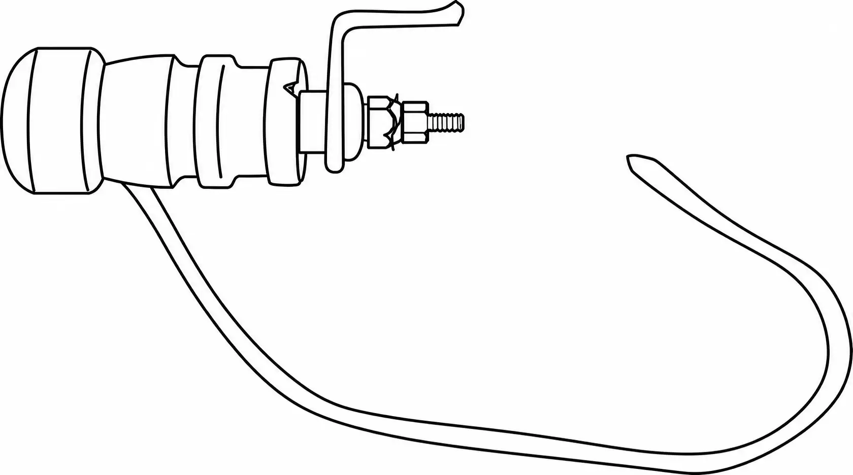
Figure 4. Lightning arrester.
High-Voltage Insulators
All power transmission lines must be isolated so as not to become safety hazards. Large strings of insulators are used at substations, and at other points along the power distribution system, to isolate the current-carrying conductors from their steel supports or any other ground-mounted equipment. Insulators may be made of porcelain, rubber, or a thermoplastic material.
Power transmission lines require many insulators in order to electrically isolate the power lines from the steel towers and wooden poles that support the lines. Insulators must have enough mechanical strength to support power lines under all weather conditions. They must also have sufficient insulating properties to prevent any arcing between the power lines and their support structures.
High-voltage insulators (see Figure 5) are usually made of porcelain. Insulators are constructed in “strings,” which are suspended from steel or wooden towers. The design of these insulators is very important since design affects their capacitance and their ability to withstand weather conditions.
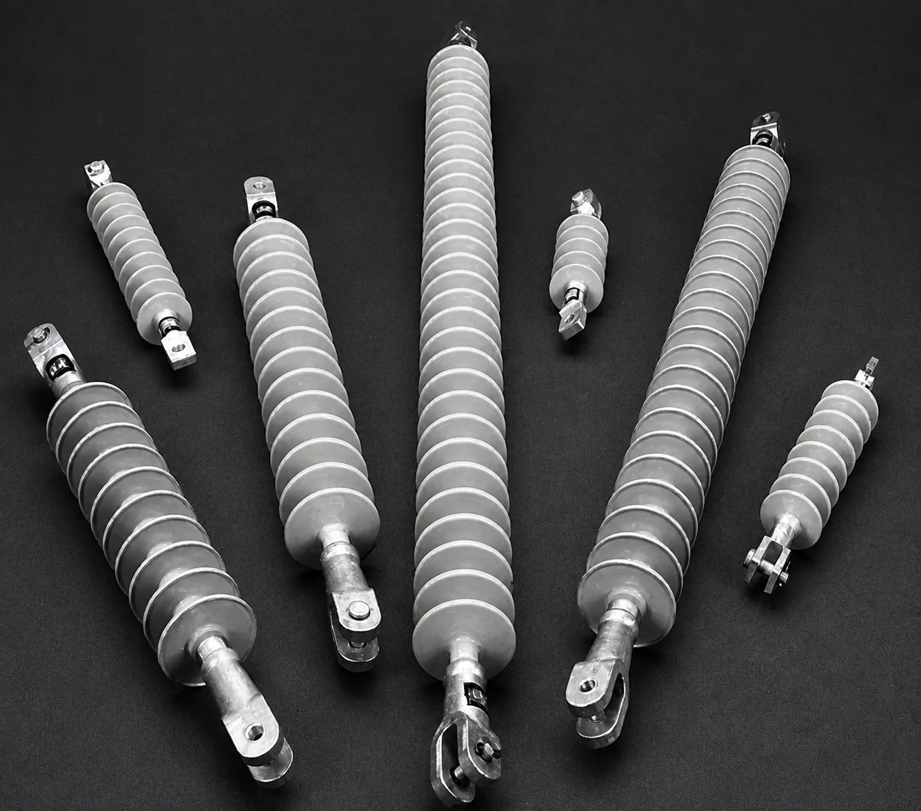
Figure 5. High-voltage insulators
High-Voltage Conductors
The conductors used for power distribution are, ordinarily, uninsulated aluminum wires or aluminum-conductor steel-reinforced (ACSR) wires for long-distance transmission, and insulated copper wires for shorter distances.
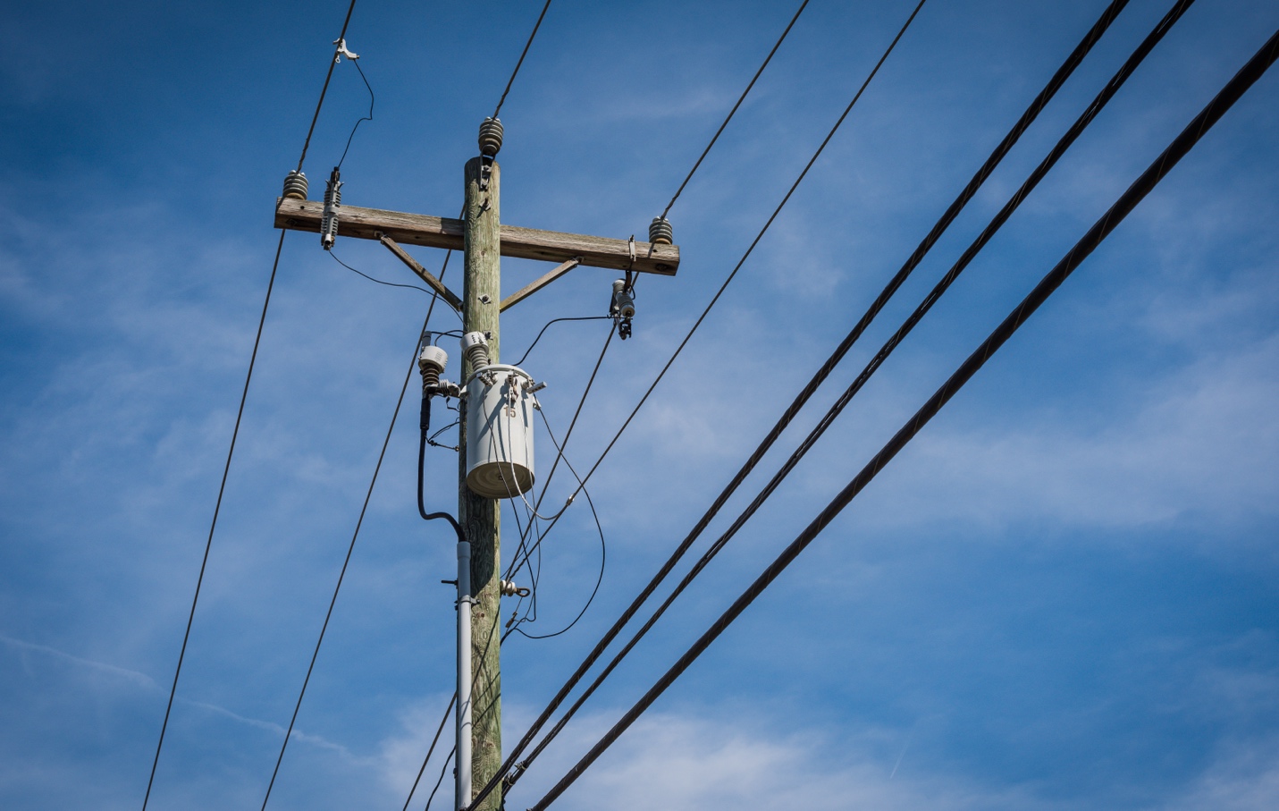
Figure 6.Overhead Power Distribution Lines
Voltage Regulators
Voltage regulators are an important part of the power distribution system. They are used to maintain the voltage levels at the proper value, as a constant voltage must be maintained in order for the electrical equipment to function properly. For instance, motors do not operate properly when a reduced or an excessive voltage is applied to them.
Transformer tap-changers, illustrated in Figure 7, may be used as voltage regulators. The secondary tap can be changed, either manually or automatically, to change the voltage output, in order to compensate for changes in the load voltage. As load current increases, line loss (I × R) also increases. Increased line loss causes the secondary voltage (Vs) to decrease. If the secondary tap is initially connected to tap No. 4, the secondary voltage can be boosted by reconnecting to either tap No. 3, No. 2, or No. 1. This can be done automatically with a motor-controlled tap changer. There are various other types of automatic voltage regulators that can be used with electrical power distribution systems.
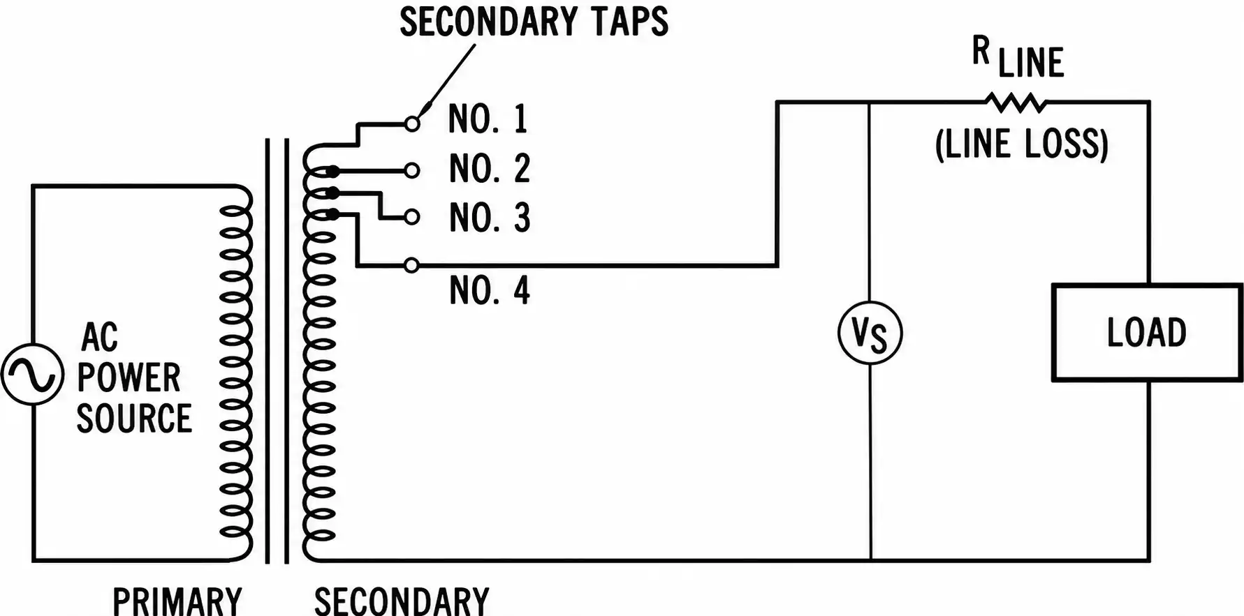
Figure 7. Transformer tap-changer voltage regulator.
Conclusion
Distribution substation components work together to ensure that electrical power is delivered safely, reliably, and at suitable voltage levels for residential, commercial, and industrial loads. Protective devices such as fuses, circuit breakers, disconnect switches, and lightning arresters help limit faults and protect equipment, while insulators and conductors support safe power transfer. Voltage regulators and transformer tap changers further help maintain acceptable voltage as system loading changes. Understanding the purpose and application of these components is therefore essential for designing, operating, maintaining, and protecting reliable distribution substations.