The article provides an overview of electric power transmission and distribution systems, explaining the concept of an infinite grid, high-voltage transmission, and various distribution methods including SWER and ring-fed systems. It also discusses balanced vs. unbalanced loads, the importance of the neutral conductor, and safety implications of a broken neutral in electrical networks.
Infinite Grid
The distribution grid is so large in comparison to most loads that it appears to be infinite, not only visually, but in most calculations as well. If a load took 100 A on each phase in a 400/230 V three-phase system, most apprentices would consider this a large load; however, a relatively small 500 MW power station can supply over 100,000 A per phase at 230 V. The entire grid has a much greater capacity than that.
What this means to the apprentice performing calculations for loads on the grid is that the voltage, frequency and phase difference between lines are fixed, and not able to be changed by any relatively small load that we apply.
Thankfully this makes calculations much easier for electricians, although engineers may still have to consider supply impedances in their calculations.
The infinite grid means fixed voltage (400/230 V), frequency (50/60 Hz) and phase separation (~15º).
Electric Power Transmission
Electrical power can be transmitted using low voltage and high current, but higher current results in higher transmission losses according to the formula E = I2RT. Therefore, to reduce what are known as I2R losses, transmission lines generally use high voltage and low current.

Figure Electric Power Transmission System
Energy is consumed in a power grid relative to the ‘load’ or current used. For the same power, the line current can be reduced by increasing the transmission voltage. This also allows for a reduction in conductor size for transmission lines and still produces a lower power loss in the line.
In economic terms, the higher the voltage used for transmission, the lower the cost of installing and maintaining the transmission lines. For long distances between the source of supply and the consumer, voltages up to 576 kV are used for power transmission and distribution. Typical voltage values vary from state to state and even within the states.
Transmission system voltages are far higher than the voltages required by the average consumer; therefore the local distribution voltage is transformed in stages at substations and sometimes in pole transformers. Figure 1 shows a simplified distribution network.
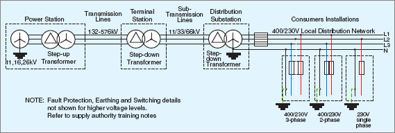
Figure 1 Electric Power Distribution
Some systems are ‘ring fed’ which means that the distribution lines form a complete circle. The reason for this is that, in the event of a fault, a small section of the ring can be shut down while the remaining sides of the ring remain online. Therefore a smaller number of consumers are affected.
Electricians must be aware of ring feeds, as two disconnections must be made to render the section safe.Most main transmission and sub-transmission lines are duplicated, and alternative routes provided, so that different localities can be fed by other lines and substations in the event of essential maintenance or breakdowns.
Swer Distribution
Rural areas are generally a special case where load units are comparatively small and their points of application are widely dispersed. One method of providing electrical power in rural areas is the Single-Wire Earth-Return (SWER) system.
Figure 2 shows an isolating transformer connected to the sub-transmission lines. The secondary voltage of the transformer is connected to a single conductor that traverses the countryside. The voltage of this line can vary between states or localities.
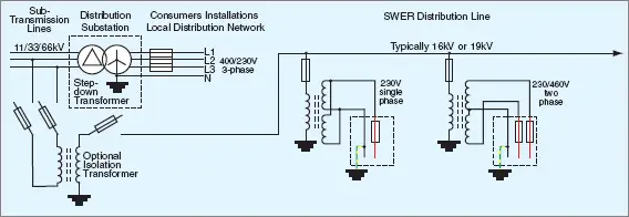
Figure 2 Single-Wire Earth-Return (SWER) distribution
If the isolating transformer is omitted and the SWER line is fed directly from one conductor of a three-phase 33 kV line, the phase voltage to earth is 4 kV. In some localities, the other phases are led out in different directions, so providing a balancing effect on the line.
Due to the high voltage, both the line currents and the earth-return currents are small. These ground currents effectively prevent the system from being used in larger population centers because, in areas where large amounts of metal are buried in the ground, electrolytic corrosion is a problem.
Special bonding arrangements might have to be undertaken to limit the amount of corrosion, and excessive metal would therefore make an SWER line uneconomical. Transformers are provided at the point of distribution. There are two secondaries on an SWER transformer which can be connected in parallel to supply 230 V or in series for 460 V at half the current.
Electric Power Distribution System
For general purposes, three-phase power may be supplied using either a 3-wire or a 4-wire system.
A 3-wire system is one that uses only the three line conductors, as shown in Figure 4 (a). The phase windings are shown connected in delta, but they can also be connected in star, with or without the star point earthed.
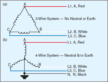
Figure 4 3-Wire Vs. 4-Wire System
For the supply authority itself, there is no great problem in supplying power with star or delta systems. For the consumer, the star system is safer and more versatile because it provides a choice of voltages and an earth reference point. Single-phase loads present a problem to an otherwise balanced three-phase system; however, single-phase loads are more convenient and safer for smaller consumers.
A 4-wire distribution system is one that uses the three line conductors plus the neutral, which is connected to the star point of the phase windings and earthed, as shown in Figure 4 (b).

Figure 3 An SWER consumer transform
A major problem in power distribution is voltage drop, resulting in those consumers furthest from the supply receiving power at a reduced voltage. Various techniques are used in attempts to overcome this difficulty.
→One method for small groups of consumers is to supply them from a centrally located transformer fed by a high-voltage primary feeder. Radiating from the central point are the secondary or supply mains, consisting of three lines and a neutral. Characteristically, the mains become smaller in size as the distance from the transformer increases. This method is typical for very small country towns.
→For higher density distribution, as in the suburbs of a larger town, it is more common to have each block of consumers supplied from a transformer, and have the mains from various blocks interconnected so that it is possible for any one consumer to be supplied from a number of sources. This method has the disadvantage of needing more protection devices for the transformers and it becomes more difficult to isolate sections of mains for maintenance purposes.
Balanced Three- Phase Loads
The loading on a three-phase system is said to be ‘balanced’ when the three lines have the same current and power factor. Under these conditions, the line currents are 15º out of phase with one another. Figure 5 shows the waveform diagram for a balanced load with three-phase currents IA, IB and IC.
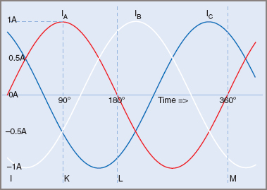
Figure 5 Current in a balanced three phase system
At the point K, the current IA is a maximum at +1 A and the currents IB and IC are both –0.5 A. At point L, the current IA is zero, IB is +0.866 A and IC is –0.866 A.
Although the three currents are all changing in value and direction, the phasor sum of the instantaneous currents is zero (IA + IB + IC = 0). Therefore, the current flowing through the neutral in a balanced circuit is also zero.
The same result can be obtained from the phasor sum of the line currents using RMS values.
For a balanced load (e.g. a three-phase motor) the neutral current is zero; thus the neutral wire is unnecessary and is usually omitted unless required for protection devices.
Where a distribution system is subject to load changes on one phase, thus putting the system out of balance, a neutral conductor becomes necessary and must be installed.
The two requirements for a balanced load are:
| 1. | Same current loading on each phase |
| 2. | Each current must have the same power factor. |
When both requirements are met, the neutral current is zero.
Unbalanced Loads
When the two conditions for balance are not met, a system is said to be ‘unbalanced’ and a current may flow in the neutral. By convention, the generated voltage is assumed to be positive when acting from the star point to the line terminal, and the phase current is also regarded as positive when flowing in the same direction.
In Figure 5, IR, IW and IB are the instantaneous values of the current in the three lines and IN is the instantaneous value of current in the neutral. The value of IN is equal to the phasor sum of IR, IW and IB, but the direction of current flow in the neutral wire is reversed.
The current in a neutral conductor of any three-phase, four-wire system is equal to minus the phasor sum of the line currents.
![]()
Note: The bar “—” above the formula represents vector quantities
Example 1
Find the value of current flowing in the neutral conductor in a three-phase, star-connected distribution system where the phase currents are …
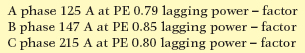
$$\textrm{ A Phase 125 A at PE 0.79 lagging power-factor}$$
$$\textrm{ B Phase 147 A at PE 0.85 lagging power-factor}$$
$$\textrm{ C Phase 215 A at PE 0.80 lagging power-factor}$$
Step 1. Convert power factors to phase angles. NB: lagging is –ve
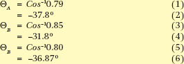
$$\Theta _{A}=Cos^{-1}0.79=-37.8^{\circ}$$
$$\Theta _{B}=Cos^{-1}0.85=-31.8^{\circ}$$
$$\Theta _{B}=Cos^{-1}0.80=-36.87^{\circ}$$
Step 2. Subtract 15º from B phase and 240º from C phase:
$$\Theta _{A}=-37.8^{\circ}$$
$$\Theta _{B}=-31.79^{\circ}-120^{\circ}=-151.79^{\circ}$$
$$\Theta _{B}=-36.87^{\circ}-240^{\circ}=-276.87^{\circ}(+83.13^{\circ})$$
Step 3. Convert polar values to rectangle values:
![]()
$$125/-37.8^{\circ}=\left [ 98.77,-76.61 \right ]$$
$$147/-156.9^{\circ}=\left [-129.54,-69.48 \right ]$$
$$215/-276.9^{\circ}=\left [18.25,214.22 \right ]$$
Step 4. Add phasors and convert to polar value:
![]()
Step 5. Find resultant by subtracting 30º:
![]()
$$IN=69.26A@102.4-180^{\circ}=69.26A@-79.58^{\circ}$$
Effects of a Broken Neutral
With single-phase loads on three-phase, 4-wire systems, it is essential that the neutral not be open-circuited.
One major reason for this precaution is personal safety. With equipment operating on one phase at 230 V, an open-circuit neutral can effectively prevent equipment from working. The appliance appears to be without power, yet still has the active conductor connected. It is possible for a person to contact the active conductor and to complete the circuit via the body to earth, and so be electrocuted.
Where the Multiple-Earthed Neutral (MEN) system is used, a break in the neutral can also create a hazardous situation. The potential of earthed appliances in some circumstances can rise to levels approaching that of the mains voltage.
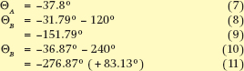
With three-phase unbalanced loads, a broken neutral causes several effects. The voltage across the lightest load increases, that across the heaviest load decreases, while the voltage across the third phase may shift either up or down.
At the same time, the power factors of the individual line currents may also be affected. Any load located before the neutral break is not affected, but single-phase loads and unbalanced three-phase loads after the break are affected. These are illustrated in Figure 6.
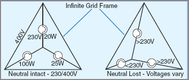
Figure 6 Lost neutral effects
To prevent the neutral from being open-circuited, neutral switches and links in substations are often locked or bolted, and neutrals are never fitted with fuses under normal installation conditions.
Electric Power Transmission & Distribution System Key Takeaways
Electric Power plays a vital role in modern society, driving everything from household appliances to industrial machinery. Understanding the structure and operation of electric power transmission and distribution systems is crucial for ensuring efficient, safe, and reliable energy delivery. Concepts like the infinite grid, high-voltage transmission, SWER systems, and load balancing directly impact how electricity is supplied to urban and rural areas alike. These principles allow engineers and electricians to minimize power loss, optimize voltage levels, and maintain system stability under various load conditions. Furthermore, recognizing the dangers of unbalanced loads and broken neutrals helps prevent hazardous situations and equipment failure.