This article discusses various methods of biasing transistors for amplifier applications, highlighting beta-dependent and beta-independent techniques and their effects on thermal stability and circuit performance.
Amplifier Bias
If a transistor is to operate as a linear amplifier, it must be properly biased and have a suitable operating point. Its steady state of operation depends a great deal on base current, collector voltage, and collector current. Establishing a desired operating point requires the proper selection of bias resistors and a load resistor to provide proper input current and collector voltage.
Stability of operation is a very important consideration. If the operating point of a transistor is permitted to shift with temperature changes, unwanted distortion may be introduced. In addition to distortion, operating point changes may also damage a transistor. Excessive collector current, for example, may cause the device to develop too much heat.
The method of biasing a transistor has a great deal to do with its thermal stability. Several different methods of achieving bias are commonly used. One method of biasing is considered to be beta-dependent. Bias voltages are largely dependent on transistor beta. A problem with this method of biasing is the transistor response. Transistor beta is rarely ever the same for a specific device. Biasing set up for one transistor will not necessarily be the same for another transistor.
Biasing that is independent of beta is very important. This type of biasing responds to fixed voltage values. Beta does not alter these voltage values. As a general rule, this form of biasing is more reliable. The input and output of a transistor are very stable, and the results are very predictable.
Beta-Dependent Biasing
Four common methods of beta-dependent biasing are shown in Figure 1. The static states of operation are a function of the transistor’s beta. These methods are rather easy to achieve with a minimum of parts. They are not, however, very widely used.
Fixed Biasing
The circuit in Figure 1(a) is a very simple form of biasing for a common-emitter amplifier. The base is simply connected to $V_{CC}$ through $R_{B}$. This causes the emitter base junction to be forward-biased. The resulting collector current is beta times the value of $I_{B}$. The value of $I_{B}$ is $V_{CC}$ divided by $R_{B}$.
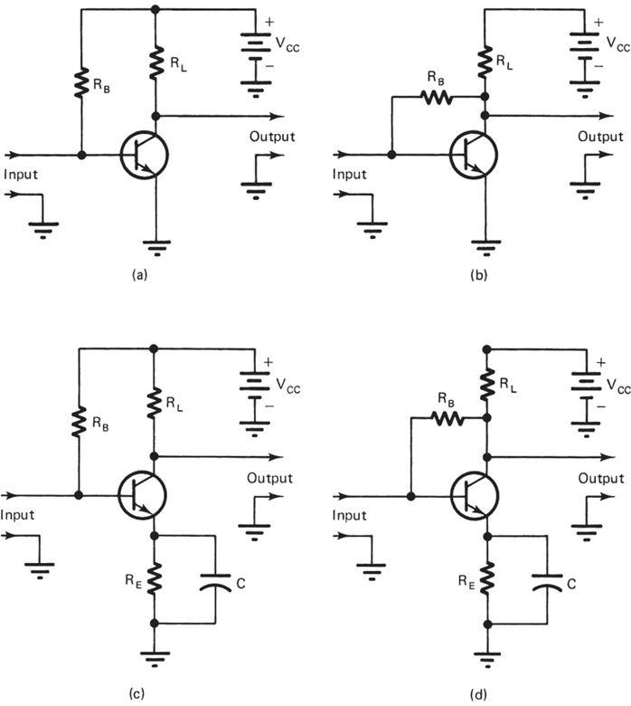
Figure 1. Methods of beta-dependent biasing
As a general rule, biasing of this type is very sensitive to changes in temperature. The resulting output of the circuit is rather difficult to predict. This method of biasing is often called fixed biasing. It is primarily used because of its simplicity.
The circuit in Figure 1(b) was developed to compensate for the temperature sensitivity of the circuit in Figure 1(a). Bias current is used to counteract changes in temperature. In a sense, this method of biasing has negative feedback. $R_{B}$ is connected to the collector rather than to $V_{CC}$. The voltage available for base biasing is that which is left over after the voltage drop across the load resistor. This is indicated as $V_{CE}$. If the temperature rises, it causes an increase in $I_{B}$ and $I_{C}$. With more $I_{C}$, there is more voltage drop across $R_{L}$. Reduced $V_{CE}$ voltage causes a corresponding drop in $I_{B}$. This, in turn, brings $I_{C}$ back to normal. The opposite reaction occurs when the transistor temperature becomes lower. This method of biasing is called self-biasing.
Fixed-Emitter Biasing
The circuit in Figure 1(c) is an example of emitter biasing. Thermal stability is improved with this type of construction. $I_{B}$ is again determined by the value of $R_{B}$ and $V_{CC}$. An additional resistor is placed in series with the emitter of this circuit. Emitter current passing through $R_{E}$ produces emitter voltage ($V_{E}$). This voltage is of opposite polarity to the base voltage developed by $R_{B}$. Proper values of $R_{B}$ and $R_{E}$ are selected so that $I_{B}$ and $I_{E}$ will flow under ordinary operating conditions. If a change in temperature should occur, $V_{E}$ will increase in value. This action opposes the base bias. As a result, the collector current drops to its normal value.
The capacitor ($C$) connected across $R_{E}$ is called a bypass capacitor. A bypass capacitor provides an alternate path around a component or to ground. In this case, it provides an AC path for signal voltages around $R_{E}$. With $C$ in the circuit, the amplifier gain is reduced. The value of $C$ is dependent on the frequencies being amplified. At the lowest possible frequency being amplified, the capacitive reactance ($X_{C}$) should be 10 times smaller than the resistance of $R_{E}$. Remember that $X_{C}=\frac{1}{2\pi fC}$ so as frequency increases, $X_{C}$ decreases.
Self-Emitter Biasing
The circuit in Figure 1(d) is a combination of circuits in Figures 1(b) and 1(c). It is often called self-emitter bias. In the same regard, the circuit in Figure 1(c) could be called fixed-emitter bias. As a general rule, emitter biasing is not very effective when used independently. The circuit in Figure 1(d) has good thermal stability. The output has reduced gain because of the base resistor connection.
Beta-Independent Biasing
Two methods of biasing a transistor that are independent of beta are shown in Figure 2. These circuits are extremely important because they do not change operation with beta. As a general rule, these circuits have very reliable operating characteristics. The output is very predictable, and the stability is excellent.
Voltage Divider Biasing
The circuit in Figure 2(a) is described as the divider method of biasing. It is used widely. The base voltage ($V_{b}$) is developed by a voltage-divider network made of $R_{1}$ and $R_{2}$. This network makes the circuit independent of beta changes. Voltages at the base, emitter, and collector depend on external circuit values. By proper selection of components, the emitter base junction is forward biased, and the collector is reverse biased. Normally, these bias voltages are referenced to ground.
The base, in this case, is made slightly positive with respect to the ground. This voltage is somewhat critical. A voltage that is too positive, for example, will drive the transistor into saturation. With proper selection of bias voltage, however, the transistor can be made to operate in any part of the active region. The temperature stability of the circuit is excellent. The divider method of biasing is often a universal biasing circuit. It can be used to bias all transistor amplifier circuit configurations.
In Figure 2(a), the base voltage ($V_{b}$) across $R_{2}$ is given by:
$$V_b = V_{cc} \frac{R_2}{R_1 + R_2} – I_b \frac{R_1 R_2}{R_1 + R_2} \approx V_{cc} \frac{R_2}{R_1 + R_2}$$
The approximation holds when
$$I_b \ll I_1 = \frac{V_b}{R_1}$$
It is also known that:
$$V_b = V_{be} + V_e = V_{be} + I_e R_e$$
For the given circuit, the base current is expressed as:
$$I_b = \frac{\dfrac{V_{cc}}{1 + \frac{R_1}{R_2}} – V_{be}}{(\beta + 1)R_e + (R_1 \parallel R_2)}$$

Figure 2 (a). Voltage Divider Biasing Diagram

Figure 2(b). Emitter Biasing Diagram
Two-Supply Emitter Biasing
The circuit in Figure 2(b) is very similar in construction and operation to that of Figure 2(a). One less resistor is used. The power supply requires two voltage values with reference to ground. A split power supply is used as an energy source for this circuit. Note the indication of $+V_{cc} \quad and \quad-V_{ee}$. The negative supply $V_{ee}$ forward-biases the emitter junction through $R_{e}$, while the positive supply $V_{ee}$ reverse-biases the collector junction.
If $R_{b}$ is sufficiently small, the base voltage will be approximately zero. Consequently, the emitter current is:
$$ I_{e} = \frac{V_{ee} – V_{be}}{R_e}$$
The value of $R_{b}$ determines the value of $I_{b}$ with only half of the total supply voltage. The values of $R_{c}$ and $R_{e}$ are usually made larger to accommodate the increased supply voltage. If $R_{e}$ is properly bypassed, the gain of this circuit is very high. Thermal stability is excellent.
Key Takeaways
Proper transistor biasing is essential for maintaining a stable operating point, ensuring consistent amplifier performance, and preventing thermal damage. Biasing methods that minimize dependency on transistor beta offer greater reliability and thermal stability compared to beta-dependent approaches. Overall, careful bias design improves predictability, enhances thermal resilience, and supports efficient and linear operation of transistor amplifiers across varying conditions.