This article explores the two important coupling techniques used in multistage amplifiers: capacitor coupling and direct coupling. These methods are essential for ensuring signal integrity and stable performance in amplification systems.
In many amplifying systems, one stage of amplification does not provide the desired level of signal output. Two or more stages of amplification are, therefore, coupled (connected) together to increase the overall gain. In most amplifying devices, the output voltage of an amplifier is greater than the input voltage. If the output of one stage is connected directly to the input of the next stage, this voltage difference can cause a problem. Signal distortion and component damage might take place. Proper coupling procedures reduce this type of problem. This article covers two methods of coupling: capacitor coupling and direct coupling.
Capacitor Coupled Amplifier
Capacitive coupling is particularly useful when amplifier systems are designed to pass AC signals. You should recall that a capacitor passes AC signals and blocks DC voltages. The capacitor selected must have low capacitive reactance ($X_{C}$) at its lowest operating frequency. This is done to ensure amplification over a wide range of frequency. Remember, capacitive reactance is an opposition to AC signals. It is also inversely related to frequency, as shown by the following formula:
$$X_{C} = \frac{1}{2\pi fC}$$
This means that if the frequency is high, the capacitive reactance will be low. If the frequency is low, the capacitive reactance will be high. As you can see, capacitive coupling has some difficulty in passing low-frequency AC signals because low-frequency AC signals create high impedance values, thus opposing the AC signal.
Large capacitance values must be selected when a good low-frequency response is desired. This is because the value of the capacitor selected is inversely related to capacitive reactance. Therefore, the capacitor selected must be of a value that keeps capacitive reactance low at the lowest operating frequency.
As you can see, the value of a coupling capacitor is a very important circuit consideration. In low-frequency amplifying systems, large values of electrolytic capacitors are normally used. These capacitors respond well to low-frequency AC. In high-frequency amplifier applications, small capacitor values are very common. The selection of a specific coupling capacitor for an amplifier is dependent on the frequency being processed. The range of frequencies within which a transistor can operate can usually be determined by examining the datasheets of the device.
A two-stage amplifier employing capacitor coupling is shown in Figure 1. Transistor Q1 is the input amplifier. Its collector voltage is 8.5 V. At the base of the second amplifier stage, Q2, the voltage is approximately 1.7 V. The voltage difference across C1 is $8.5 – 1.7$ V, or 6.8 V. The capacitor isolates these two operating voltages. It must have a DC working voltage value that withstands this difference in potential. For example, a capacitor with a DC working voltage of 50 V signifies the maximum voltage that can be applied to it in a specific application. The working voltage for the capacitor being used for coupling the two stages in Figure 1 should have a value in excess of 6.8 V.
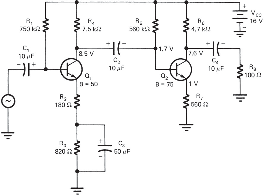
Figure 1. Two-stage capacitor-coupled amplifier.
Direct Coupled Amplifier
In direct coupling, the output of one amplifier is connected directly to the input of the next stage. In a circuit of this type, a connecting wire or conductor couples the two stages. Circuit design must take into account device voltage values. This type of coupling is an outgrowth of the divider method of biasing. A transistor acts as one resistor in a divider network. The output voltage of one amplifier is the same as the input voltage of the second amplifier. When the circuit is designed to take this into account, the two can be connected together without isolation.
Figure 2 shows a two-stage direct-coupled transistor amplifier. Note that the signal passes directly from the collector of Q1 into the base of Q2. The base current ($I_{B}$) of transistor Q2 is developed without a base resistor. Any $I_{B}$ needed for Q2 also passes through the load resistor R3. The collector voltage $V_{C}$ of Q1 remains fairly constant when the two transistors are connected. Note also that the emitter bias voltage of Q2 is quite large (7.2 V). The base emitter voltage ($V_{BE}$) of Q2 is the voltage difference between $V_{B}$ and $V_{E}$. This is 7.8 $V_{B}$ – 7.2 $V_{E}$ or 0.6 $V_{BE}$. This value of $V_{BE}$ forward biases the base emitter junction of Q2. In direct-coupled amplifiers, each stage has a different operating point based on a common voltage source. Several direct-coupled stages supplied by the same source are rather difficult to achieve. As a general rule, only two stages are coupled by this method in an amplifying system.
Direct-coupled amplifiers are very sensitive to changes in temperature. The beta of a transistor, for example, changes rather significantly with temperature. An increase in temperature causes an increase in beta and leakage current. This tends to shift the operating point of a transistor. All stages that follow amplify according to the operating point shift. Changes in the operating point can cause nonlinear distortion or a lack of stability.
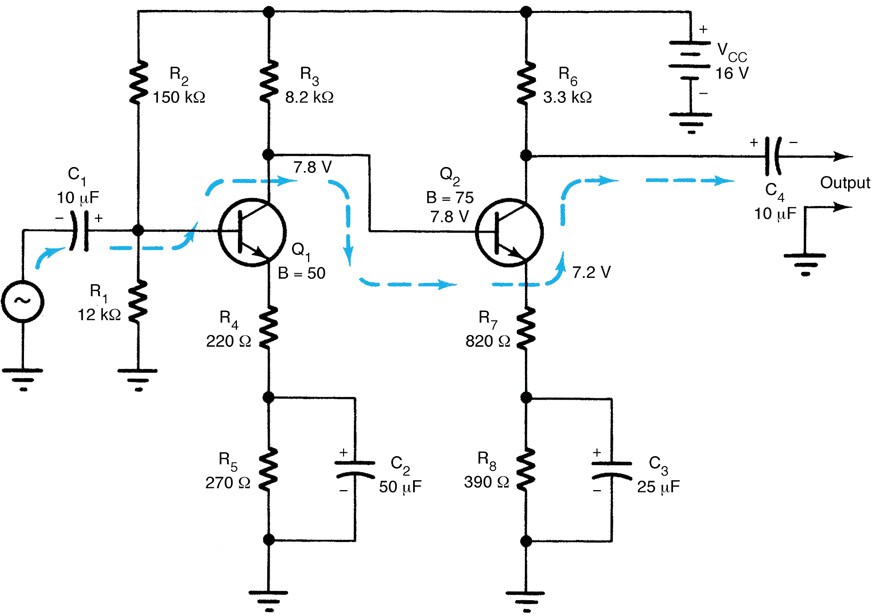
Figure 2. Two-stage direct-coupled amplifier.
When two transistors are directly coupled, it is often called a Darlington amplifier. The transistors are usually called a Darlington pair. Two transistors connected in this manner are also manufactured in a single case. This type of unit has three leads. It is generally called a Darlington transistor. The gain produced by this device is the product of the two transistor beta values. If each transistor has a current gain ($\beta$) of 100, the total current gain is $100 \times 100$, or 10,000. Figure 3 shows a Darlington transistor amplifier circuit.
Darlington amplifiers are used in a system where high current gain and high input impedance are needed. Only a small input signal is needed to control the gain of a Darlington amplifier. In effect, this means that the amplifier does not create a heavy load for the input signal source. The output impedance of this amplifier is quite low. It is developed across the emitter resistor, R3. A Darlington amplifier has an emitter-follower output (common collector circuit). Several different transistor combinations are used in Darlington amplifiers.
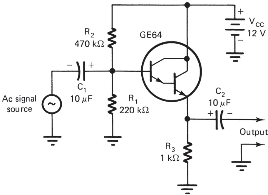
Figure 3. Darlington transistor amplifier.
Review Questions
- Capacitive coupling is especially useful for passing ______ signals.
- The capacitive reactance $X_{C}$ is ______ related to frequency.
- In capacitive coupling, large capacitors are used for ______ frequency response.
- Direct coupling connects amplifier stages without using ______ components.
- A Darlington pair has a total current gain equal to the ______ of the individual transistor gains.
- In a Darlington amplifier, the output is taken across the ______ resistor.
- Temperature variations in direct-coupled amplifiers can cause changes in the transistor’s ______.
- The base current $I_{B}$ of Q2 in direct coupling also flows through ______.
Answers
- AC
- inversely
- low
- coupling
- product
- emitter
- beta
- R3
Key Takeaways
Understanding amplifier coupling methods is essential for designing stable and efficient multistage amplifier systems. Capacitive coupling allows AC signal transfer while blocking DC, direct coupling simplifies biasing but is sensitive to temperature, and Darlington pairs offer high current gain with minimal input. These methods are widely used in audio systems, communication devices, and signal processing applications, where maintaining signal quality and proper impedance matching are crucial.