The article discusses the applications of thyristor control, focusing on reduced-voltage motor starters and the use of triacs for switching and power control in various circuits. It explores how thyristors like SCRs and triacs are employed to regulate voltage, control lamp brightness, and manage power flow in AC loads.
Silicon-controlled rectifiers (SCRs) are used in reduced-voltage motor starters to reduce the amount of voltage delivered to a motor upon starting. Figure 1 shows a three-phase, SCR reduced-voltage starter power circuit made up of two contactors: a start contactor (C1) and a run contactor (C2). The operation of the circuit can be summarized as follows:
- For this application the SCR delivers a varying amount of power to the motor by means of phase angle control.
- When the motor is first started, the start contacts (C1) close, and reduced voltage is applied to the motor through the reverse-parallel-connected SCRs.
- Triggering of the SCRs is controlled by control circuits that chop the applied sine-wave system power so that only a portion of the wave is applied to the motor.
- The voltage is then automatically increased until the motor is at full-line voltage.
- At this point, the run contacts (C2) close, and the motor is connected directly across the line and runs with full power applied to the motor terminals.
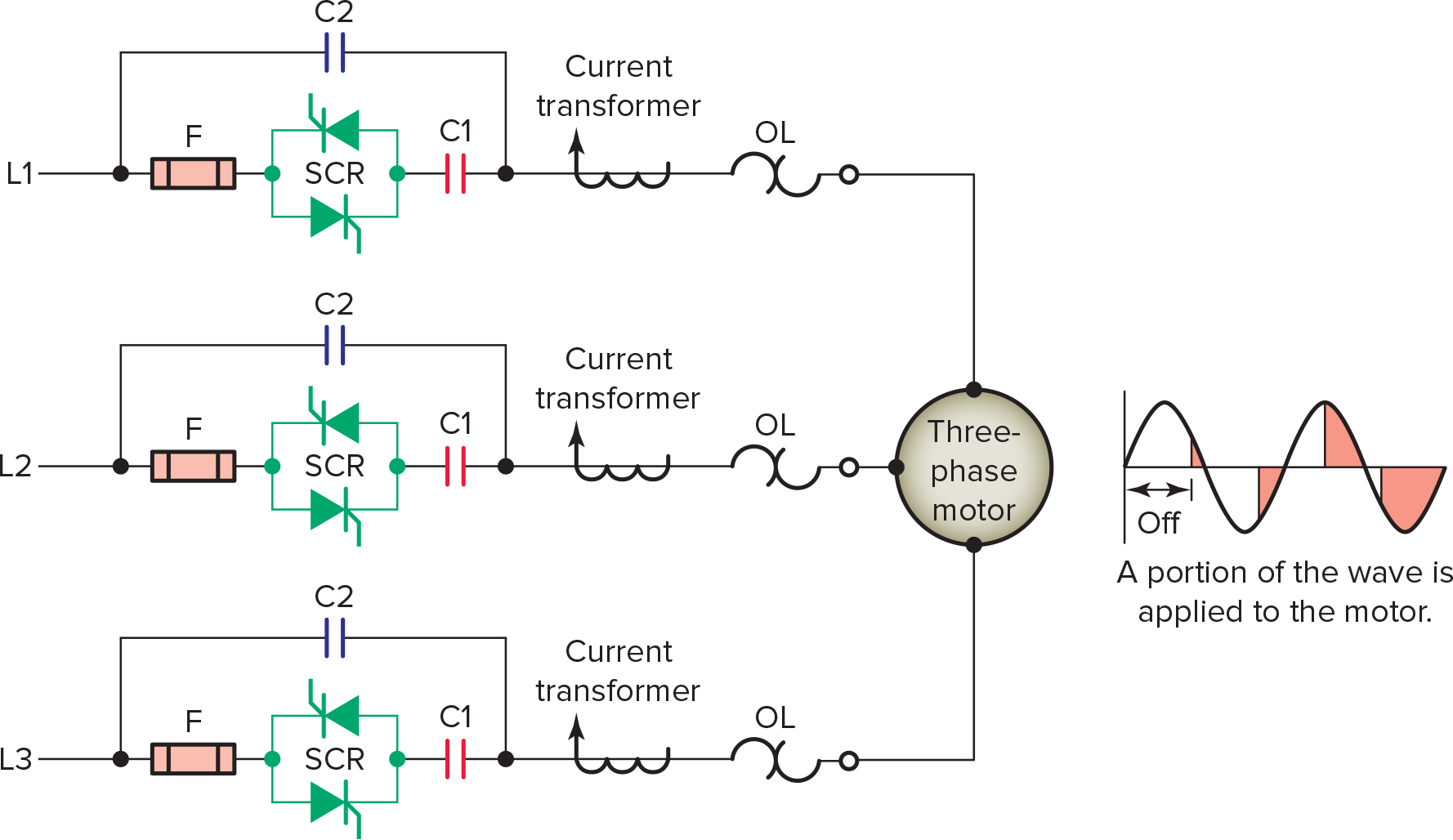
Figure 1. Three-phase, SCR reduced-voltage starter power circuit.
Switching AC Power Loads with Triac
The triac is a bidirectional electronic switch, which means it can conduct current in either direction. This operating characteristic makes the triac an ideal component for switching AC power loads. Figure 2 illustrates how a triac is used to switch the AC voltage to control the on/off state of a lamp. The output module of a programmable logic controller (PLC) serves as the link between the PLC’s microprocessor and field load devices. An optical isolator separates the output signal from the PLC processor circuit from the field load devices. The operation of the circuit can be summarized as follows:
- As part of its normal operation, the processor sets the outputs on or off according to the logic program.
- When the processor calls for the lamp to be on, a small voltage is applied across the LED of the optical isolator.
- The LED emits light, which switches the phototransistor into conduction.
- This, in turn, switches the triac into conduction to turn on the lamp.
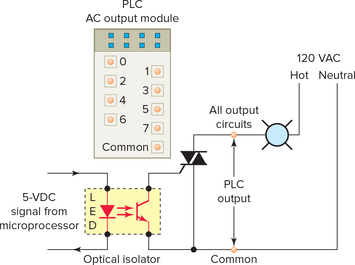
Figure 2. Triac switching of a PLC output module.
Manage Power Flow in AC Loads with Triac
In addition to switching, a triac can be used to vary the amount of power supplied to an AC load, as illustrated in Figure 3. When used for this type of application, a control triggering circuit is needed to ensure that the triac conducts at the proper time. The operation of the circuit can be summarized as follows:
- The trigger circuit controls the point on the AC waveform at which the triac is switched on. It proportionally turns on a percentage of each power line half-cycle.
- The resulting waveform is still alternating current, but the average current value is adjustable.
- Since the trigger can cause it to trigger current in either direction, it is an efficient power controller from essentially zero to full power.
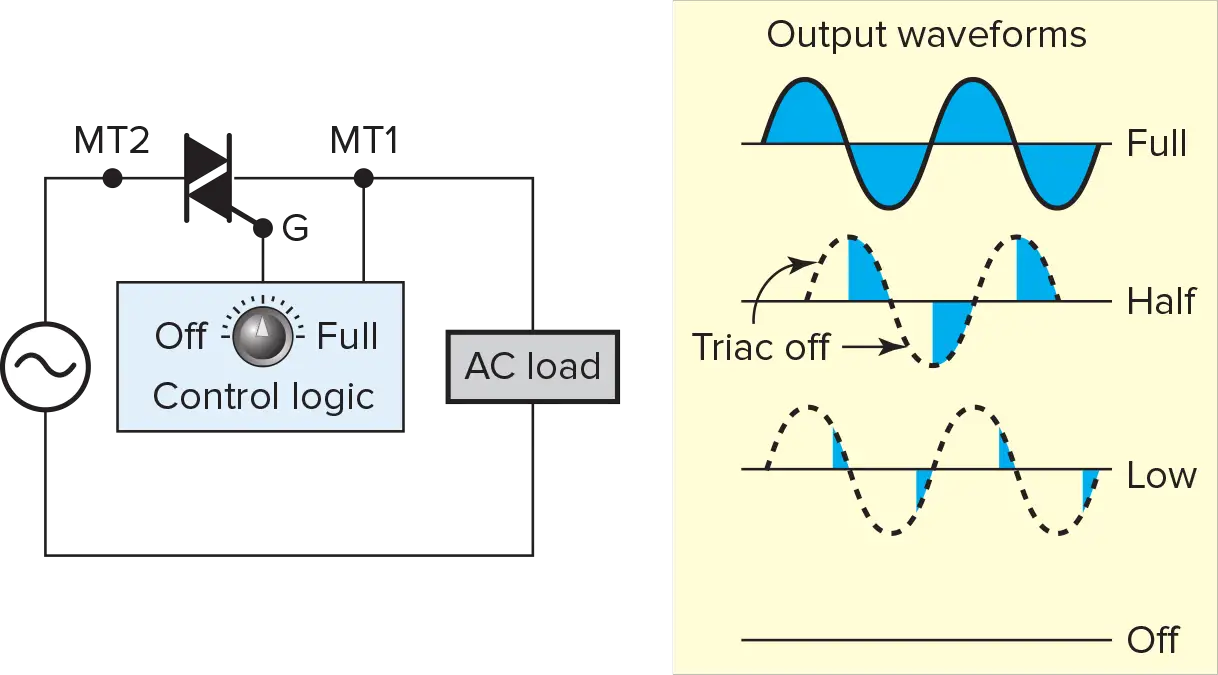
Figure 3. Triac variable-power circuit.
Control Lamp Brightness with Triac
Most lamp dimmer switches are manufactured with a triac as the power control device. A simplified triac incandescent lamp dimmer circuit is shown in Figure 4. The operation of the circuit can be summarized as follows:
- The diac is a two-terminal device that behaves like two diodes connected in opposite directions. Current flows through the diac whenever the voltage across it reaches its rated breakover voltage.
- With the variable resistor set to its lowest value, the capacitor will charge rapidly at the beginning of each half-cycle of the AC voltage.
- When the voltage across the capacitor reaches the breakover voltage of the diac, the capacitor voltage discharges through the gate of the triac.
- Thus, the triac conducts early in each half-cycle and remains on to the end of each half-cycle.
- As a result, current will flow through the lamp for most of each half-cycle and produce maximum lamp brightness.
- When the resistance of the variable resistor is increased, the time required to charge the capacitor to the breakover voltage of the diac increases.
- This causes the triac to fire later in each half-cycle. So, the amount of time current flows through the lamp is reduced, and less light is emitted.
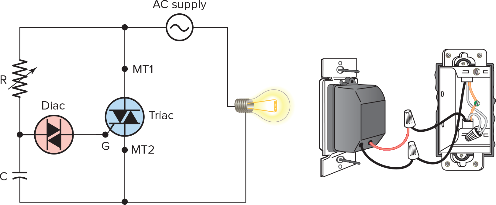
Figure 4. Triac incandescent lamp dimmer.
Thyristor Control Key Takeaways
The application of thyristor control, particularly through devices like silicon-controlled rectifiers (SCRs) and triacs, plays a crucial role in modern electrical systems. By enabling reduced-voltage motor starters, efficient lamp dimming, and precise power control in AC loads, thyristors offer significant advantages in terms of energy efficiency, operational flexibility, and equipment longevity.