The article discusses special types of transformers, focusing primarily on instrument transformers—potential transformers (PTs) and current transformers (CTs)—and their roles in safely measuring high voltages and currents. It also covers transformer configurations such as multiple secondary windings, tapped windings, and touches on safe handling practices and design considerations for accurate measurement and protection.
Instrument Transformers
It is unsafe to connect instruments and allied equipment to high voltage and current circuits, so instrument transformers are used to reduce these voltages and currents to safer, more convenient values. The two types of instrument transformers used are potential and current transformers. Figure 1(overleaf) shows how a voltmeter, an ammeter and a power meter are connected to high-voltage lines by means of voltage and current transformers.
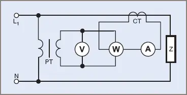
Figure 1 PT/CT power measurement
Potential Transformers (PT or VT)
The potential or voltage transformer operates on the same principle as the power transformer, where the ratio of the primary and secondary voltages is proportional to the turns ratio of the primary and secondary windings (i.e. V2 ∞ V1).
Potential transformers are designed to have a standard output voltage when the full rated voltage is applied to the primary windings. For single-phase work, AS/NZS 1243 specifies a secondary voltage of 110 V; where transformers are used in the star connection for control work in substations, the standard output voltage for each transformer is 63.5 V, giving a line-to-line voltage of 110 V.
The secondary voltage is connected to the appropriate loads such as voltmeters, wattmeters and protection relays. The VA ratings of potential transformers are quite small as instruments require little energy to operate. One terminal of the secondary winding is often earthed as an added safety measure in the event of a breakdown in the insulation between primary and secondary windings.
The Standard symbol for a PT is shown in Figure 2 and a typical PT is shown in Figure 3. The four terminals of a PT are designated and care must be taken to see they are correctly connected and the two voltage systems appropriately isolated.
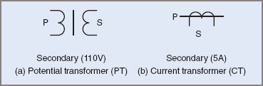
Figure 2 Potential and current transformer symbols
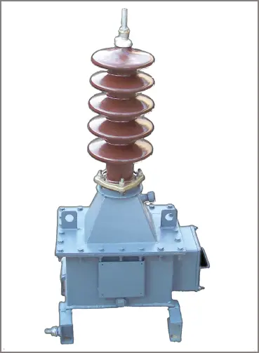
Figure 3 Potential transformer
The physical features are similar to those of a power transformer except that the primary has to be insulated for a much higher voltage and is often immersed in oil for extra protection.
The important factor with potential transformers is the accuracy of the voltage ratio and the elimination of phase-angle errors. The energy levels being measured are generally large and therefore losses in the transformer are inconsequential compared to the power levels.
A phase angle of 0°E is desirable (180°E is also acceptable), particularly where a PT has to supply such instruments as wattmeters, which have more than one operating coil.
As a general guide, a potential transformer usually operates at low flux densities in iron cores of relatively large cross-sectional areas. The copper conductors have few turns and are large in cross-section for the small current taken.
Potential Transformer Burden
A PT is also assigned a load or burden rating. This gives an indication of the available full-load secondary current and also the load placed on the supply source. For example, a 200 VA potential transformer at 110 V would make available approximately 1.8 A of secondary current for meters and relays:
![]()
Current Transformers (CT)
In a power transformer, the flux density in the core is high, the primary current depends largely on the secondary current and the voltage ratio is the main consideration. However, for the current transformer the core flux density is very low, the secondary current is connected across a low impedance load and therefore depends directly on the primary current, and the current ratio is the main consideration.
The primary winding of a current transformer is connected in series with the load and consists of one or a few turns of a heavy gauge conductor, often a copper bus-bar. The impedance of the primary winding is therefore so low that the primary current I1 is not affected by the secondary load but depends on the external load connected in the primary circuit.
The secondary circuit consists of the current coils of ammeters, wattmeters and protective relays that are all low impedance loads. The secondary circuit is always closed, so the secondary current produces a flux, which opposes the primary flux, greatly limiting the flux density of the core and therefore any load on the primary. The current ratio is equal to the inverse of the turns ratio and so there are more turns on the secondary winding.
Why the secondary of CT is short circuited?
If the secondary becomes open-circuited, there will be no secondary flux to oppose the primary flux, and so the core flux density increases. Owing to the large ratio of secondary to primary turns, and the excessive core flux, the induced voltage at the secondary terminals increases greatly, producing a safety hazard and the possibility of insulation breakdown.
The greater core flux might also cause excessive heat losses and saturation in the core. Consequently the secondary of a current transformer must never be open-circuited under any circumstances and a suitable short-circuiting link is normally provided for connection across the secondary terminals when the instruments are disconnected.
Note: The secondary of a current transformer must never be open-circuited under any circumstances.
Current transformers are made in a number of forms, depending on requirements and current ratios. Some types have primary windings that have more than one turn, while others are variations of the one-turn primary stage.
One variation of the single-turn primary type has a short straight conductor passing through a hole in the iron core that forms part of the transformer’s construction.
Another type has an opening in the iron core and the transformer is slipped over the bus-bar or cable. Some current transformers have a secondary winding wound on a circular iron core, which is also slipped over the bus-bar adjacent to a circuit breaker or power transformer.
The standard for current transformers (AS/NZS 1675) specifies two values or current range—1 A and 5 A. The higher value is still used in many instances, but increasing use is being made of the lower value, especially in substation work where the instrumentation and control relays are some distance away from the transformers.
At the lower value of current, the resistance and impedance of the cable is of relatively less importance. A current transformer suitable for use in a high-voltage sub-station is shown in Figure 4.
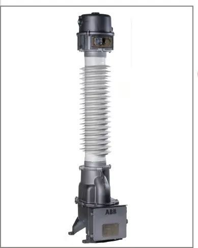
Figure 4 Current transformer
Current Transformer Burden
Current transformers are designed to measure line currents without affecting the load in any way. Consequently, while a CT might be able to handle high or low currents, the burden it imposes must be as low as possible (e.g. 5 VA). The CT must have a load on the secondary at all times, therefore the burden will exist at all times, causing a small voltage drop in the primary conductor at the point of the CT placement.
Safe Working Procedures
Potential transformers
Potential transformers are designed to restrict the high voltage to a designated area and conduct a safe lower voltage to a monitoring point where it can be connected to instruments or relays. The secondary voltage should always be proportional to the primary voltage.
One of the secondary terminals is usually earthed and care must be taken in the choice of instruments and their handling to ensure that an additional earth is not introduced at some other point within the circuit.
In some cases a non-magnetic, electrostatic shield is installed between the primary and secondary windings during manufacture. This shield is earthed as a means of protection for the operator as well as removing electrostatic interference and noise. When connecting meters to a PT, a short-circuit across the terminals must be avoided as with any high-impedance device.
Current transformers
Current transformers are used to handle high currents while providing a proportional current to normal instruments on AC. The CT isolates the supply voltage from the operator and at the same time smaller conductors can be taken from the CT to the measuring location.
The secondary of a CT must never be open-circuited as to do so would allow high voltages at the terminals. With most CTs and associated instruments a shorting link is provided. Any connecting or disconnecting in CT circuits must follow a standard operating procedure that ensures the CT is not open-circuited at any stage.
An additional factor that should be taken into account is that an open circuit, apart from the high secondary voltage problem, can also lead to magnetic saturation occurring within the core that can affect the accuracy of the CT for future use.
Current transformers must have all the windings held firmly in place to withstand the magnetic forces created during overloads, current surges and fault conditions. The secondaries often have one side of the winding earthed for protection and, in some cases, a non-magnetic screen between the windings.
Transformers with Multiple Secondaries
There are instances where more than one secondary voltage is desired. The choice is then one of having two or more transformers to obtain the voltages or having one transformer with one primary winding and more than one secondary.
On occasion it could be mandatory from a safety point of view to have separate transformers but it is common and cheaper to have one transformer with a slightly larger core and have as many secondaries as required. This is illustrated in Figure 5, where a transformer is shown with three secondary windings, each having different voltages. These extra windings may be called ‘tertiary’ windings.
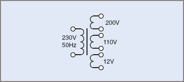
Figure 5 Tertiary winding transformer
The current and voltage ratios still hold true for the individual windings but it should be kept in mind that the volt-ampere rating of the transformer will be the sum of the individual ratings of each winding. For example, to use the windings at ratings of 50 VA, 55 VA and 40 VA, the transformer as a whole would have to be rated at the sum of these figures, or 145 VA.
If due regard is given to phasing the windings, it is only one further step to connect all three windings in series and have a total voltage of 322 V. This procedure then produces a winding with taps brought out at various voltages.
Tapped Windings
Particularly for smaller transformers, it is common to see primary and secondary windings with tappings brought out to give a range of voltages from a common point. This method of obtaining various voltages is shown in Figure 6.
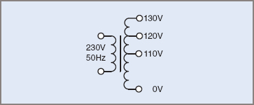
Figure 6 Tapped windings
While the taps are shown here on the secondary windings, it must be appreciated that the method is not restricted to secondary windings. It also quite common for tapped primary windings to reflect a range of acceptable primary supply voltages, such as 220/230/240 V.
Once the ‘turns per volt’ ratio of a transformer is established it is a straightforward matter of calculating the required number of turns to determine the location of a voltage tap on the winding.
A rule of thumb commonly used in winding rooms during the author’s apprenticeship stated 7 turns per volt per square inch of iron, referring to the cross-sectional area of the laminations in the window in the coil.
Using that rule of thumb, winding rooms could convert an existing transformer to a new voltage secondary. Note that the rule of thumb related to common laminations of the day and modern materials will probably allow lower numbers of turns.
Remember the volt–ampere rating of the transformer has to be observed so converting a 24 V transformer to a 12 V transformer will allow for twice the current output assuming the winding conductor is an appropriate CSA.
Autotransformers
An autotransformer has a part of the winding common to both the primary and the secondary circuits (see Figure 7).
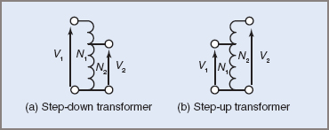
Figure 7 Autotransformers
The voltage across any number of turns is proportional to the turns per volt established into the primary winding. Therefore, for simplicity, assume a certain transformer has one volt per turn, and is connected across a 230 V supply. It would require 230 turns. If, however, it was intended to also provide the correct output voltage at either 220 V or 240 V, there might be a tapping at 220 turns and another at 240 turns.
Autotransformers, like other transformers, may be step-up or step-down, meaning the secondary may be a higher or lower voltage than the primary voltage.
If a voltmeter were placed between the common (neutral) terminal and each of the tappings in turn, the meter would read 220 V, 230 V and 240 V respectively. A load connected to one of the terminals would be provided with that voltage and a current allowed by the VA rating of the transformer.
In this way a device designed to operate on 240 V could be supplied from a 230 V supply (or 220 V, or 240 V) simply by selecting the appropriate tapping of the primary winding.
Autotransformers are usually considered not to have a secondary winding but the output may be referred to as secondary and indeed there may be a secondary or even tertiary winding included.
Standard AS/NZS 3000 indicates the limitations placed on the use of autotransformers for general use. In general, the Standard stipulates that except in special circumstances the secondary voltage should not vary by more than ±25 per cent of the primary voltage.
Variac Transformers
Extending from the concept of an autotransformer, a transformer could have a tapping on every turn, making the range of output voltage almost continuous.
‘Variac’ is a common trade name for a transformer which is an autotransformer having a toroidal winding with an exposed side, cleaned of insulation so a moving ‘wiper’ can be adjusted along the winding, thus making an apparently continuously variable voltage. In fact the voltage would only vary in steps according to the volts per turn if the wiper didn’t cover more than one turn.
The circuit diagram for a Variac is shown in Figure 8, while Figure 9 shows the windings and wiper arm.
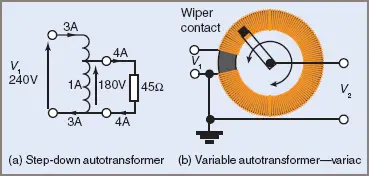
Figure 8 Variable voltage autotransformers
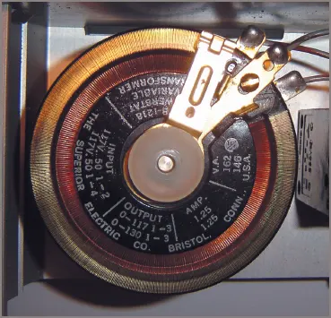
Figure 9 Variac-style transformer
Isolation Transformers
An isolation transformer is a type of transformer that has an equal number of turns on the primary and secondary windings. That means of course that the output voltage is equal to the supply voltage.
Isolation transformers have two basic uses—one is providing isolation from the supply voltage so a machine that has a potential earth fault can be tested without dropping out the RCDs. Of course care must be taken when working in such environments.
Another purpose is in testing circuits with a reduced risk of fault current, as the current is limited by the impedance and VA of the transformer.
Isolation transformers were once commonly used on worksites to operate power tools with a reduced risk of earth faults and are still used in testing RCDs for compliance to the standards.
The theory of using isolation transformers is that the output is unrelated to earth and therefore an operator would need to make contact with both sides of the transformer to cause a shock situation.
High-Reactance or Flux Leakage Transformers
When designing transformers, the highest possible efficiency is usually desired and design features are incorporated to reduce the leakage flux. In some applications, however, transformers with poor efficiency may be deliberately designed to meet particular requirements.
One such transformer, called a high-reactance or leakage transformer, produces a very high no-load voltage and a comparatively small short-circuit current.
The design is such as to permit a low flux leakage on no-load, but a high flux leakage on increasing load. This is achieved by spacing the primary and secondary windings some distance apart on the core and by using either fixed or variable magnetic shunts (see Figure 10).
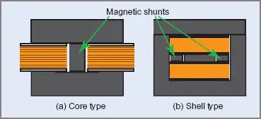
Figure 10 Flux leakage transformer
On no load, the primary winding produces a flux in the core which cuts the secondary winding, inducing a voltage in it. The leakage flux is reasonably low because the air gaps in the magnetic shunt circuits produce a reasonably high reluctance in the shunt circuits. The secondary voltage can be calculated using the usual transformation ratio.
When the transformer is loaded however, the secondary current produces a flux that opposes the primary flux, causing some of the primary flux to be diverted through the magnetic shunts, thus reducing the value of flux cutting the secondary turns. This reduces the value of secondary voltage at an increasing rate.
Figure 11 shows the secondary voltage decreasing as the load current increases. Transformers using this principle are found in such applications as furnace ignition, gaseous discharge lighting and welding machines.
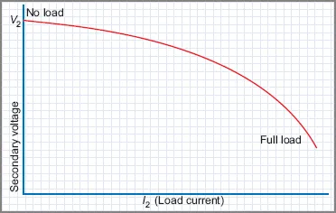
Figure 11 Flux leakage transformer load curves
Long narrow cores can achieve the same result as magnetic shunts, the length of the core governing the degree of leakage. Distribution transformers have a small leakage factor built into them as protection against excessive currents in the event of transmission line failures.
Welding Transformers
Welding transformers (not electronically controlled) generally used flux leakage or shunted flux techniques to control the amount of current delivered to the welding rod. Most cheap home welders, and even many high power welders, still use this basic technique.
Figure 12 shows the transformer of a typical home welder including the flux shunt which is adjustable for varying the welding current.
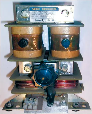
Figure 12 Flux-shunt welding transformer
Special Transformers and Applications Key Takeaways
Special types of transformers—particularly instrument transformers like Potential Transformers (PTs) and Current Transformers (CTs)—play a vital role in modern electrical systems by enabling the safe and accurate measurement of high voltages and currents. Their ability to isolate measurement instruments from dangerous power levels ensures the protection of both equipment and personnel. The use of multiple secondary windings, tapped windings, and proper safe-handling techniques further enhances their versatility and precision in applications ranging from power metering and control to protective relaying and substation operations.