This article covers various types of protective relays, such as overcurrent, directional, and differential relays, highlighting their operating characteristics and applications in electrical systems.
Different Types of Protective Relays
What is a Protective Relay?
A protective relay is an electronic device used in power systems to monitor and analyze electrical parameters, such as current, voltage, and frequency, and to take action to protect electrical equipment and ensure system stability. Its primary function is to detect abnormal conditions, such as faults, overloads, or imbalances, and then initiate a corrective response, such as tripping a circuit breaker, to isolate the affected part of the system.
The operating characteristics of the more commonly used protective relays are described in this article.
A protective relay is said to pick up when it operates to open its normally closed (NC) contact or to close its normally open (NO) contact in response to a disturbance to produce a desired control action. The smallest value of the actuating quantity for the relay to operate is called its pickup value.
A relay is said to reset when it operates to close an open contact that is normally closed (NC) or to open a closed contact that is normally open (NO). The largest value of the actuating quantity for this to happen is called the reset value.
How Does Overcurrent Relay Work?
An overcurrent relay is a protective device designed to monitor electrical current levels and operate when the current exceeds a predetermined threshold, called the pickup value. It primarily functions to protect electrical equipment from damage due to excessive currents caused by faults or abnormal operating conditions.
The key actuating quantity in an overcurrent relay is current. The relay is designed to compare the monitored current with its pickup value, which can be adjusted via tap settings. When the current equals or exceeds this value, the relay initiates its operation. Overcurrent relays are generally classified into two types:
1. Instantaneous Overcurrent Relay
Operation __ This relay operates without intentional time delay and responds almost immediately to current surges. Depending on the magnitude of the fault current, its operating time ranges from 1/2 to 3 cycles of the power frequency.
Use Case __ It is typically employed where quick disconnection is critical, such as in zones where high-speed fault clearing is essential to prevent cascading failures.
Adjustment __ The pickup value can be set independently, ensuring flexibility to suit specific protection requirements.
2. Time-Delay Overcurrent Relay
Operation __ The operating time of this relay is inversely proportional to the magnitude of the fault current. Higher currents result in faster operation, while lower currents lead to delayed tripping.
Time-Dial Adjustment __ The time-delay characteristic can be shifted up or down using a time-dial setting, which modifies the delay for a given fault current.
Use Case __ It is widely used in layered protection schemes to coordinate with other relays, ensuring selectivity and minimizing unnecessary disconnections.
One inherent limitation of overcurrent relays is their non-selective operation. They tend to detect overcurrents not only within their designated protection zones but also in adjacent zones, leading to potential miscoordination.
Proper coordination of pickup values and time-delay settings between relays in different zones can improve selectivity. Coordination ensures that only the relay closest to the fault operates first, while others remain inactive unless needed.
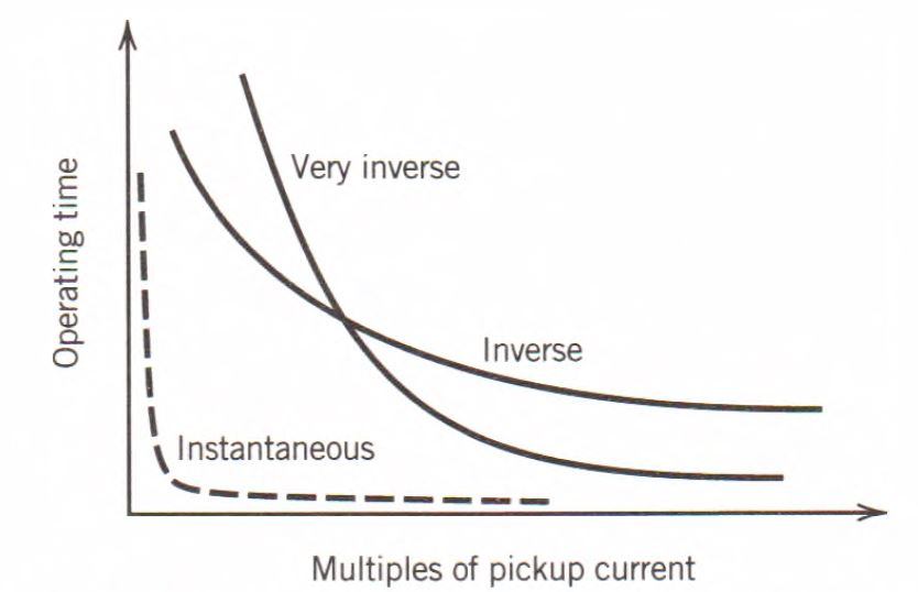
Figure 1. Time characteristics Curves of overcurrent relays.
How Does Directional Relay Work?
Directional relays are advanced protective devices capable of distinguishing the direction of current flow in an electrical system. Unlike traditional relays that respond solely to the magnitude of current, directional relays operate based on the phase angle relationship between the actuating current and a reference quantity, such as a voltage or current. This reference quantity is known as the polarizing quantity. By analyzing this phase angle, the relay determines the direction of power flow and triggers a protective action only for specific directional faults.
The directional relay works by comparing the phase angle of the fault current with the polarizing quantity. This polarizing quantity provides the relay with a reference for the direction of current flow. When the fault current aligns with the relay’s predefined directional settings, the relay operates. Conversely, if the current flows in the opposite direction, the relay remains inactive.
This capability is achieved using a combination of measuring circuits and phase detectors inside the relay. By leveraging this directional sensitivity, the relay ensures precise fault detection and avoids unnecessary tripping for faults occurring outside its zone of protection.
Applications in Power Systems
Directional relays are essential in electrical systems where fault direction significantly impacts system stability and protection coordination. Their applications include:
Parallel Feeders __ In systems with parallel transmission lines, directional relays help identify which line the fault has occurred on, ensuring that only the faulty line is isolated.
Ring Main Systems __ In ring distribution systems, directional relays ensure that faults are cleared in the appropriate section, preventing disruption to unaffected parts of the system.
Transformer and Generator Protection __ These relays are often used to protect transformers and generators where power flow direction changes during normal and abnormal conditions.
Integration with Overcurrent Relays
Directional relays are frequently combined with overcurrent relays to enhance selectivity. While the overcurrent relay responds to excessive current levels, it cannot discern the fault’s location relative to the relay’s position. This limitation can lead to non-selective tripping, where multiple relays operate for the same fault.
By incorporating a directional element, the relay system becomes capable of determining the fault’s direction and operating only when the fault is within its designated protection zone. This improves coordination between relays in adjacent zones, minimizing the likelihood of widespread outages or misoperation.
How Does Differential Relay Work?
The operation of a differential relay is based on the vector difference of two or more similar electrical actuating quantities.
The most common application is current differential relaying, in which the current entering and the current leaving the protected element are compared. If the difference exceeds the pickup value of the relay, it operates to trip the breakers to isolate the element.
Typical differential relaying employing an overcurrent relay is shown in Figure 2. Identical current transformers are placed at both ends of the protected element, and the CT secondaries are connected in parallel with an overcurrent relay.
The directions of current flows shown in Figure 2 are those corresponding to normal load conditions or to a fault external to the protected element. Thus, it is seen that the CT secondary currents merely circulate between the CTs, and no current flows in the overcurrent relay.
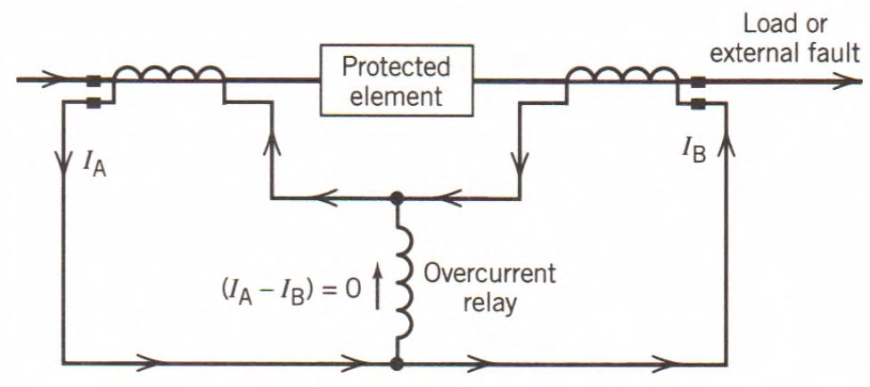
Figure 2. Differential Relay Working Principle
Suppose a fault occurs on the protected element as shown in Figure 3. The short-circuit currents flow into the fault, and the CT secondary currents no longer circulate. The vectorial sum of the CT secondary currents flows through the overcurrent relay and causes the relay to disconnect the element from the system.
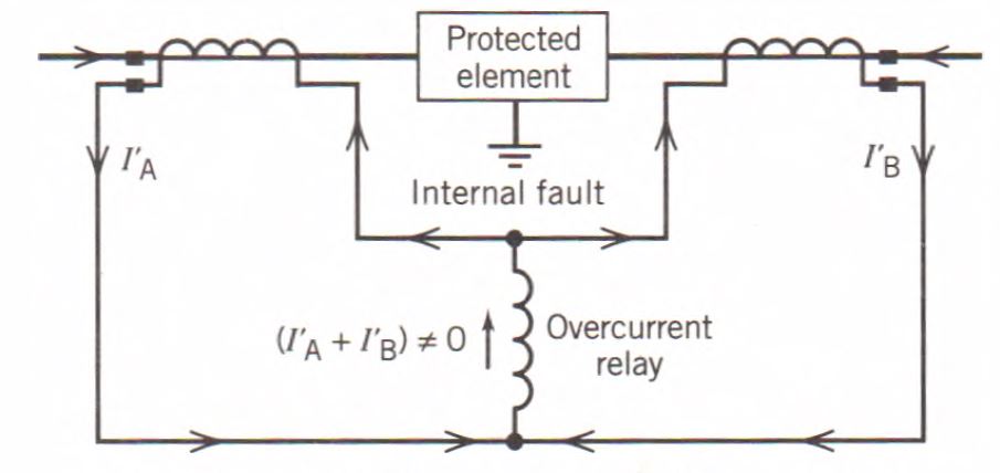
Figure 3. Fault currents detection with a differential relay.
Even though the current transformers used for the differential relay are identical, the secondary currents may not be identical because of CT transformation inaccuracies. Thus, the secondary currents will no longer merely circulate for normal load conditions or for external faults. The differential current that will flow through the overcurrent relay may be sufficient for the relay to pick up and cause false tripping of the circuit breakers.
Percentage-Differential Relays
The difficulty encountered in differential relaying due to CT errors is eased by the use of a percentage-differential relay. This type of relay has an operating coil and two restraining coils. The operating current is proportional to (IA – IB) and must exceed a certain percentage of the restraining current, which is proportional to 1/2(IA + IB) before the relay will operate.
How Does Distance Relay Work?
In a distance relay, a voltage and a current are balanced against each other, and the relay responds to the ratio of the voltage to the current, which is the impedance of the transmission line from the relay location to the point of interest. The impedance may be used to measure distance along a transmission line, hence the name distance relay.
The key principle of a distance relay is its ability to measure the impedance of the transmission line. The impedance is directly proportional to the physical distance from the relay to the fault. During normal operating conditions, the impedance seen by the relay is high because the line is clear, and the voltage at the relay location remains high relative to the current.
In the event of a fault, the current increases significantly, while the voltage drops. This causes the measured impedance to decrease. When the impedance falls below a pre-set threshold (pickup value), the relay identifies this as a fault and operates to isolate the affected section of the line.

Figure 4. Distance Relay Operation
Types of Distance Relays
There are several types of distance relays, each tailored to specific system requirements and fault conditions:
Impedance Relays
An impedance relay operates based on the measured impedance of a transmission line, which is determined by the ratio of voltage to current. It is primarily used for protection of transmission lines, where it identifies faults by calculating the line impedance between the relay’s location and the fault point. Since impedance is proportional to the distance along the line, this relay is often associated with distance protection schemes.
Working Principle of Impedance Relays
The impedance relay compares the measured impedance of the line with a pre-set value known as the pickup impedance. If the measured impedance falls below the set value, it indicates a fault within the protected zone, and the relay operates to isolate the affected section.
The relay functions by continuously monitoring the voltage and current at its location and calculating the line impedance using the formula:
$$Z = \frac{V}{I}$$
Where:
Z is the impedance.
V is the line voltage.
I is the line current.
When a fault occurs, the current increases, and the voltage at the fault point drops significantly, leading to a lower impedance value. The relay operates if the measured impedance is less than or equal to the set value.
Characteristics of Impedance Relays
1. Operating Region __ Impedance relays operate when the measured impedance lies within a specific region on the impedance plane (usually a circular or oval region). This operating region is defined by the relay’s settings.
2. Non-Directional Nature __ Impedance relays, in their basic form, are non-directional. They respond to faults in all directions. However, for directional selectivity, they are often combined with directional relays.
3. Time-Dependent Operation __ The impedance relay can be designed with a time-delay feature. The closer the fault, the quicker the relay operates, ensuring faults within the primary zone are cleared promptly while faults in adjacent zones are delayed.
In modern power systems, impedance relays are often supplemented with directional elements or combined with other relays (e.g., mho or reactance relays) to improve fault discrimination and reliability. Advanced numerical relays incorporate impedance measurement as part of their multi-functional protection schemes, enhancing speed, accuracy, and adaptability to system conditions.
Reactance Relays
Reactance relays are designed to measure the reactance component of a transmission line’s impedance while disregarding the resistive component. This makes them highly effective in detecting faults in scenarios where the resistance can vary significantly, such as in the case of arcing faults or heavily loaded lines. By focusing solely on reactance, they ensure reliable fault detection irrespective of resistive fluctuations.
Reactance relays are particularly advantageous for ground fault detection because the fault path resistance can vary widely depending on soil conditions or arc resistance. Despite these resistive variations, the relay maintains its sensitivity by concentrating on the reactance component.
Additionally, reactance relays are non-directional, meaning they respond to faults irrespective of the fault current’s direction. This makes them versatile for certain applications, although directional relays may be added to enhance selectivity in more complex systems.
Mho Relays
Mho relays, also known as admittance relays, are directional by design. They only respond to faults occurring in a specific direction from their location. Their operating characteristic is a circular boundary in the impedance plane, making them ideal for long transmission lines where fault directionality is critical. Mho relays are often preferred in applications requiring enhanced selectivity, as they inherently block faults occurring in the reverse direction.
Distance relays are indispensable for protecting high-voltage transmission systems. Their ability to measure impedance allows them to determine the fault’s location with remarkable accuracy. This makes them particularly useful in:
Zone Protection __ Distance relays are configured to operate within specific zones, ensuring faults are isolated precisely without impacting adjacent zones.
Long Transmission Lines __ For extended transmission networks, distance relays are ideal because they maintain consistent performance over varying line lengths and load conditions.
Backup Protection __ In addition to serving as primary protection, distance relays often provide backup protection for adjacent zones, ensuring system reliability even if the primary protection fails.
How Does Pilot Relay Work?
Pilot relaying is a means of communicating information from the end of a protected line to the protective relays at both line terminals.
The relays determine whether a fault is internal or external to the protected line. The communication channel, or pilot, is used to transmit this information between line terminals. If the fault is internal to the protected line, all the circuit breakers at the terminals of the line are tripped at high speed. If the fault is external to the protected line, the tripping of the circuit breakers is prevented or blocked.
Three types of pilots are commonly used for protective relaying: wire, power line carrier, and microwave pilot.
A wire pilot consists of a twisted pair of copper wires of the telephone line type. It may be leased from the telephone company, or it may be owned by the electric utility.
The power line carrier is the most commonly used pilot for protective relaying. In this type of pilot, a low-voltage, high-frequency current (30 to 300 kHz) is transmitted along one phase of the high-voltage power line to a receiver at the other end of the protected line. Line traps, located at both line terminals, serve to contain a carrier signal inside the zone of the protected line.
The microwave pilot is an ultra-high-frequency radio system operating above 900 MHz. In this pilot, transmitters and receivers operate the same way as in a power line carrier pilot; however, line traps are replaced by a line-of-sight antenna.