The article provides an overview of inverter types, functions, and applications, particularly distinguishing between stand-alone, grid-tied, and battery backup inverters. It also covers key concepts like power factor correction, synchronization with the grid, and anti-islanding protection for safety and efficient grid integration.
In addition to types of output waveforms, inverters are also classified according to the interface as either stand-alone or grid-tied. Another inverter configuration, known as a battery backup inverter, is simply an inverter with a built-in charge controller.
Stand-alone inverters are used for small applications such as powering a specific piece of equipment or providing power to a private residence or small business.
Grid-tied inverters, also known as grid-interactive inverters, are used mainly in larger systems that can supply power to the electrical grid.
Some inverters are used in both modes where excess power in a small application is fed to the grid for credit. Only simplified systems are shown here to illustrate the functions of an inverter.
The stand-alone inverter is used in applications where all of the output power is used for a specified load, such as an appliance with an AC motor, and is independent of the electrical grid.
The grid-tied inverter is used in applications where all or part of the output power can be sent to the electrical grid. For example, a home solar power system may give excess power not used in the home to the power company for credit if net metering is available.
A large solar power system is usually devoted entirely to producing power for the electrical grid. The power company provides single-phase sinusoidal voltage and current to a residence or small business at a voltage of 240 V rms and at a frequency of 60 Hz.
The 240 V is split into two 120 V lines for most home and small business applications. Some large appliances, such as clothes dryers and stoves, require the full 240 V.
Power Factor Correction
A single-phase sine wave inverter (both stand-alone and grid-tie) produces one output voltage. One complete cycle of a voltage sine wave goes from 0° to 360°, as shown in Figure 1a.
In Figure 1b, current and voltage are 90° out-of-phase; that is, a phase difference of 90° exists between them. This is the case with a purely inductive load and no actual power is delivered to the load.
In Figure 1c, the current and voltage are in phase; that is, no phase difference exists between them. The output current and voltage of an inverter are designed to be in phase for a purely resistive load.
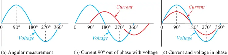
Figure 1 Single Phase Voltage and Current
Power Factor
The phase difference between current and voltage determines the power factor.
If the load is a pure capacitance or pure inductance, the voltage and current are 90° out of phase with each other and the power factor is 0. In this case, all the power is reactive power, which is returned to the source and no true power is delivered to the load.
If the load is pure resistance, the voltage and current are in phase with each other and the power factor is 1, so all of the power is delivered and dissipated in the load.
When the load is a combination of resistance and reactance (which is usually the case), the power factor is somewhere between 0 and 1.
If the power factor is less than 1, power factor correction is necessary to increase the power factor to as close to 1 as possible.
For power factor correction, one type of reactance is added to cancel the effects of the opposite type of reactance in the load, making the load appear to be purely resistive.
The diagram in Figure 2 is a common method to illustrate power factor. If there is inductance or capacitance in the load, there will be reactive power plotted on the y-axis.
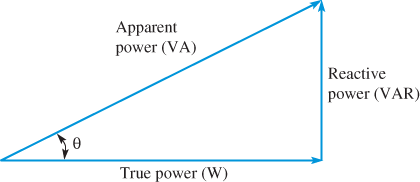
Figure 2 Power Triangle. The sides of the right triangle are related by the Pythagorean Theorem.
The resistance in the load accounts for the true power. Apparent power (Pa) is the vector (trigonometric) sum of reactive power (Pr) and true power (Ptrue).
The angle (θ) shown between the true power and the apparent power is the same as the phase angle between current and voltage.
The units of power are the watt (W) for true power, the volt-amp reactive (VAR) for reactive power, and the volt-amp (VA) for apparent power. The three powers form a right triangle, so by the Pythagorean Theorem:
\[P_{a}^{2}=P_{true}^{2}+P_{r}^{2}\]
The power factor (PF) is expressed as:
\[PF=cos(\theta )\]
Cos is an abbreviation for “cosine,” which is a trigonometric function. On the scientific calculator, simply enter the phase angle and press the COS key.
Most reactive loads tend to be inductive. Appliances with motors, such as air conditioners, refrigerators, washing machines, and dryers, are typical inductive loads. For these types of loads, power factor correction is achieved by the addition of capacitors in parallel with the connected motor circuits.
The amount of capacitance required depends on the type of motor and the type of inverter, including the type of waveform.
In general, it is important to check with the user manual or the inverter manufacturer before attempting any external power factor correction with an inverter. An incorrect value of capacitance can damage an inverter.
Power Factor Correction Example
- If the true power is 50 W and the reactive power is 10 VAR, determine the apparent power.
- If the phase angle is 20° determine the power factor.
Solution
- Take the square root (use the √x key) on both sides of Equation mentioned above:
\[{{P}_{a}}=\sqrt{{{\left( 50W \right)}^{2}}+{{\left( 10VAR \right)}^{2}}}=51VA\]
2. PF = cos 20° = 0.94
Synchronization with the Grid
A grid-tied inverter must synchronize its output voltage with the grid voltage in terms of frequency, phase, and amplitude.
Ideally, the grid maintains a power factor of 1; this number can vary within specified limits, but it is usually very close to 1. This means that the current and voltage from the grid are ideally in phase, as are the current and voltage from the inverter.
When a grid-tied inverter is synchronized, it is at the same frequency and phase as the grid. Also, the voltage amplitude of the inverter must be a bit higher than the grid for the inverter to supply current to the grid.
The two basic synchronization methods are the phase-locked loop and zero-crossing detection.
Phased-Locked Loop
A phase-locked loop can be used to accomplish synchronization of the inverter current to the grid voltage.
Because the inverter acts as a current source to the grid, this provides a direct correlation of inverter current to grid voltage.
The phase-locked loop uses a phase detector to measure the phase of the inverter current and compare it with the phase of the grid voltage.
A feedback loop is used to force the inverter current phase to match the grid voltage phase. Figure 3 shows the concept of an inverter with phase-locked loop synchronization. The green block represents the basic inverter circuits.
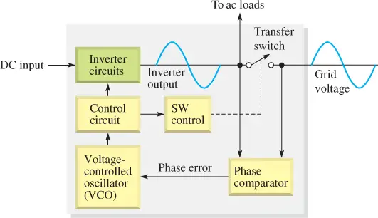
Figure 3 Phase-Locked Loop Synchronization in a Grid-Tied Inverter
The phase comparator compares the phase of the inverter output to the phase of the grid voltage (reference voltage) and issues an error voltage proportional to the phase difference.
The is error voltage fed back to the voltage-controlled oscillator (VCO) to move the phase of the inverter output closer to the phase of the grid voltage.
When the phase difference between the grid voltage and the inverter voltage is zero, the error voltage is zero (or near zero) and an in-phase condition is established. During this synchronization process, the transfer switch is open.
The transfer switch is a switch used to connect a source to the grid.
Once the voltage and current are in phase, the transfer switch closes and the inverter is then connected to the grid.
Zero-Crossing Detection
An alternate method for verifying that the inverter and grid are synchronized is to check the zero crossings of each wave.
Zero-volt crossings occur when a sine wave switches polarity: at 0°, 180°, and 360°.
A sine wave crosses the zero-volt axis in the positive direction at 0° and at 360° and in the negative direction at 180°.
The crossing times of the grid are compared to the crossing times of the inverter output, and the difference in the two waves are used by control circuits to synchronize the two waves.
During the synchronization process, the transfer switch is open to avoid connecting the inverter to the grid. Once synchronization is established, the transfer switch is closed and the inverter is connected to the grid.
Anti-Islanding
When utility workers are working on a power line, most utility operating procedures, including the National Electrical Safety Code (NESC), require that the line is isolated from all generating sources.
Islanding occurs when a grid-tied renewable energy source (called a distributed generation [DG] resource), continues to operate and provide power to a certain location and remains connected to the electrical grid after the grid no longer supplies power.
DGs can be any type of renewable energy source, such as a solar or wind system that is connected to the grid.
The term islanding comes from the idea that, when a portion of the grid goes down and thus causes a blackout, a location that still has power from a DG is isolated and surrounded by darkness (no power) like an island surrounded by the sea.
An island can be as small as a single residence or as large as an entire community. Figure 4 illustrates the basic idea.
Anti-islanding is a protective feature of a grid-tied inverter that detects a power outage by monitoring parameters of the AC voltage at the point of common connection (PCC) and disconnecting from the grid with the transfer switch that is often part of the inverter.
The transfer switch can switch from the grid to the distributed generator if it is used for backup only.
If the DG is used in conjunction with the grid on a continuous basis, the transfer switch simply disconnects the DG from the grid.
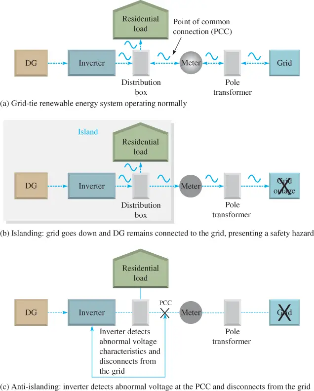
Figure 4 Islanding and Anti-Islanding Detection
As stated before, the reason for anti-islanding is to protect utility company personnel who are working on the power lines as a result of the grid outage.
If renewable energy systems remain connected to the grid when an outage occurs, the power supplied by these systems to the grid is hazardous to the workers and can also damage any equipment connected to the grid at other distribution points. The standards for anti-islanding protection are UL1741 and IEEE1547.
Two factors sometimes make detection of islanding difficult.
One is that the voltage generated by the inverter is identical to the grid voltage. The other is a motor that is part of a load on the grid may continue to spin and initially act as a generator with a frequency close to the original line frequency (although it will eventually slow down). It may be hard to distinguish either of these sources from the grid voltage.
Three basic types of detection are used for sensing islanding for grid-tied inverters: passive detection, active detection, and utility notification.
- Passive detection
Generally, most inverters detect the islanding condition by detecting a sudden change in system frequency, voltage magnitude, phase, or power. One or more of these parameters are monitored, and the inverter is shut down within a specified time when these parameters vary from specified limits.
- Active detection
In this method, a disturbance is injected and the response is measured. For example, the inverter current may be altered and the response to this change depends on the type of load to which the inverter is connected.
Typically, a grid-tied inverter is connected to the user load and the grid. If the grid becomes disabled, the load changes and causes a predictable response to the disturbance.
- Utility Notification
For utility notification, the power company knows when it removes power and issues a signal to the inverter to disconnect from the grid.
Maximum Power Point Tracking
When an inverter is used in a system that has no backup batteries and therefore no charge controller, the MPPT is built into the inverter. Because the inverter input comes directly from the solar array, the MPPT in an inverter operates the same as one for a charge controller.
Inverter Review Questions
- What is power factor?
- What is the purpose of synchronization in an inverter?
- What is islanding and why must it be avoided?
- What are three ways to detect islanding?
Answers
- The phase difference between current and voltage determines the power factor, which is the cosine of the angle between the current and the voltage or between the true power and the average power.
- Synchronization makes the inverter voltage the same frequency and phase as the grid voltage.
- Islanding is when a grid-tied renewable energy source continues to operate and provide power to a certain location and remains connected to the electrical grid after the grid no longer supplies power. Islanding must be avoided to protect utility company personnel who are working on the power lines as a result of the grid outage.
- Passive detection, active detection, and utility notification
Inverter Functions & Application Key Takeaways
Understanding the various types of inverters—stand-alone, grid-tied, and battery backup—and their core functions such as power factor correction, synchronization, and anti-islanding protection is essential due to their critical roles in modern power systems. These concepts ensure safe, efficient, and reliable integration of renewable energy sources into the electrical grid. Stand-alone inverters provide independence for remote or small-scale applications, while grid-tied systems maximize energy efficiency by feeding surplus power back to the grid. Battery backup inverters enhance reliability by offering uninterrupted power during outages. Features like power factor correction improve energy delivery efficiency, synchronization ensures seamless grid interaction, and anti-islanding safeguards utility workers and infrastructure during outages.