In this section, we will describe the operation of the synchronous generator. Figure 1 shows a cross-section of a round-rotor synchronous generator, and Figure 2 shows a cross-section of a salient-pole synchronous generator.
Both are two-pole synchronous generators. The primary difference between the two types is evident from looking at these two figures. The round-rotor synchronous generator has a uniform air gap, which means the self-inductance of the stator coils does not depend on the position of the rotor. The salient-pole generator, on the other hand, has a varying air gap.
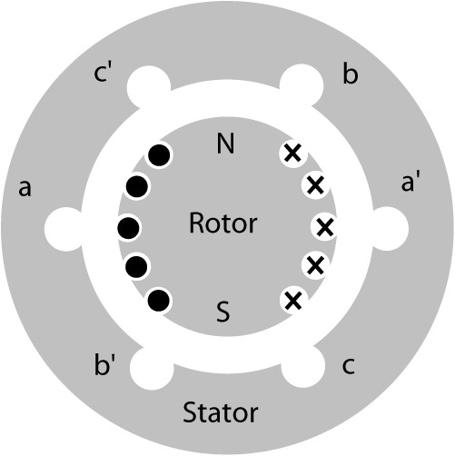
Figure 1: Cross section of a round-rotor synchronous generator.
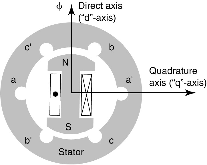
Figure 2: Cross section of a salient-pole synchronous generator.
If we define the direct axis of the rotor as being through the center of the pole-faces, we note the air-gap is much smaller along the direct axis than in a direction perpendicular to the direct axis.
The axis that is perpendicular to the direct axis is called the quadrature axis. The result of the varying air gap is that the stator self-inductances are time-varying. The salient-pole synchronous generator thus has a direct-axis reactance and a quadrature-axis reactance, which must be accounted for when analyzing a salient-pole synchronous generator.
Synchronous Generator Operation
When the field is rotated by a prime mover, voltages are induced in the stator coils because they are cutting the flux of the rotor field.
Note that the stator coils shown in Figures 1 and 2 are physically 120° apart. If the rotor is rotated at constant speed, then the voltages induced in the stator windings are 120° apart in time.
Further, the phase sequence of the generated voltage will depend on the direction the synchronous generator is driven. The generators shown in Figures 1 and 2 will produce an ABC sequence if the generator is driven in the clockwise direction and a CBA sequence when driven in the counterclockwise direction.
If a balanced, three-phase load is connected to the synchronous generator while voltages are induced in the coils, currents will flow from the generator to the load. Since the voltages are a balanced three-phase set, the currents will also be a balanced three-phase set.
The stator currents produce a rotating magnetic field in the airgap of the generator that rotates at synchronous speed. In essence, the generator has two rotating magnetic fields, one due to the rotation of the rotor field and one due to the MMF of the stator windings.
The frequency of voltages and currents in the stator windings is determined by the speed of the rotor, and the stator field rotates in synchronism with the rotor. The magnetic field of the stator combines with the magnetic field of the rotor to produce the resultant airgap flux.
When the rotor is driven by a prime mover, its field pulls the stator field along with it. The rotor field and the resultant field are separated by the power angle or torque angle, δ, as shown in Figure 3.
The solid arrow indicates the axis of the rotor’s magnetic flux, while the dashed arrow indicates the direction of the resultant flux for generator operation. The assumed direction of rotation is in the clockwise direction, as shown.
Note that the south pole of the resultant flux lags behind the north pole of the rotor field. The rotor field essentially drags the resultant flux along with it and torque is created by the separation of the fields, due to the magnetic attraction of the opposite poles.
In the generator, a mechanical torque is applied to the shaft to turn the generator and the electromagnetic torque opposes the direction of rotation.
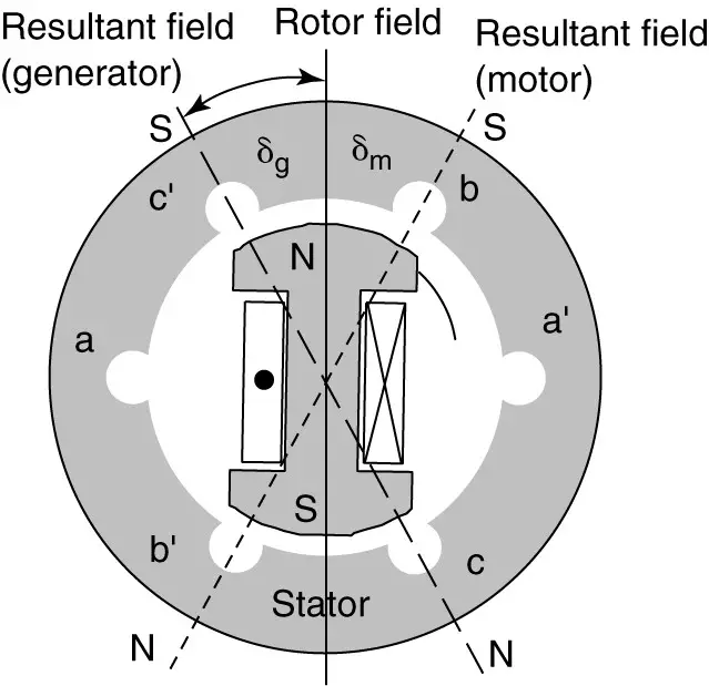
Figure 3: Power angle of the synchronous generator.
As an analogy, we could consider the rotor to be fastened to the stator by rubber bands. As we try to turn the rotor (apply a load), the rubber bands resist the motion. Further, the more we turn the rotor, the more force would be applied by the rubber bands. Eventually, if we went too far, the rubber bands would break. The situation in the generator is similar. As we apply more input torque, the angle gets bigger and the generator delivers more electrical power, but if it gets too big (> 90°) the generator will lose synchronism.
As the load changes on the synchronous generator, the phase currents and stator field also change. In particular, the power angle changes when the load changes. This can actually be observed by shining a strobe lamp on the shaft. When the load changes, the shaft appears to move when illuminated by the strobe.
In order for the angle between the fields to change, the speed of the synchronous generator must change at least momentarily. In fact, the speed tends to oscillate about synchronous speed, a process called hunting. To reduce hunting, an additional winding can be added to the synchronous generator.
The lamination in the following Figure has a series of holes punched just behind the pole-face.

Figure: Lamination of the rotor (Courtesy of Caterpillar Inc.)
When the rotor is constructed of a stack of laminations, those holes are filled with aluminum and the aluminum bars thus formed are shorted together at each end of the rotor pole. This forms a portion of a squirrel-cage winding under each pole-face. The purpose of this winding is to damp out speed transients, and it is thus called the damper winding.
Figure 4(a) shows the top view of a salient rotor with a damper winding, and Figure 4(b) shows a side view of the damper winding. The damper winding may or may not be visible on the pole-face of a real synchronous generator.
Dampening Winding Function in Synchronous Generator
When the synchronous generator runs at synchronous speed, the damper winding bars do not cut any magnetic flux, so no voltage is induced in the bars. When the generator speed varies from synchronous speed, however, voltages are induced in the damper winding bars, which cause currents to flow because the bars are shorted together. The interaction of the damper winding currents with the rotating magnetic flux creates induction motor-type torques on the rotor that bring it back toward synchronous speed.
Damper windings are also referred to by other names, such as killer winding since they kill the speed transients, or amortisseur winding, which comes from the French for the assassin. The damper winding also plays a role when the synchronous generator is started as a motor.
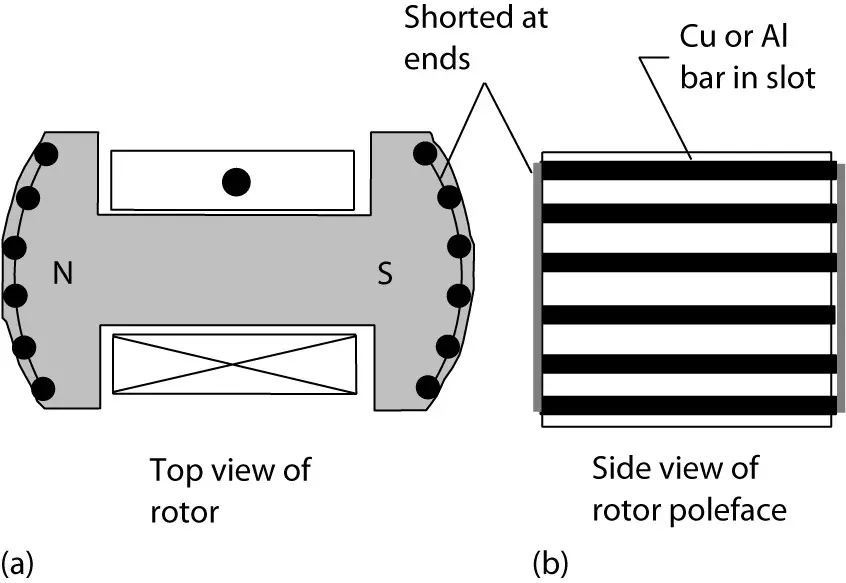
Figure 4: Damper winding on a synchronous generator.
Synchronous Generator Key Takeaways
Understanding the detailed operation of synchronous generators—including the differences between round-rotor and salient-pole designs, the role of the power angle, and the function of damper windings—is essential for their effective application in modern power systems. These concepts directly impact the stability, efficiency, and reliability of power generation. For instance, the ability of the generator to maintain synchronism under varying loads is critical for uninterrupted power supply, especially in grid-connected systems. The inclusion of damper windings to minimize oscillations (hunting) ensures smoother operation during load transients and enhances the generator’s ability to respond dynamically to system changes.