This article covers the circuit design of a Zener diode voltage regulator, including component selection and power dissipation considerations.
The main components for a voltage regulator consist of a Zener diode and a series resistor. The Zener diode must have a $V_{Z}$ value and a power dissipation rating that will accommodate the circuit ratings. The series resistor must be selected to accommodate the range of voltages used. It must also have a wattage rating that will accommodate the total current.
Voltage Regulator Design
Regulator design requires some knowledge of the circuit being controlled and the values of voltage and current being accommodated. Let us assume that the unregulated output of a power supply ranges from 20 to 15 V. The desired regulated voltage is 12 V, and the load current will range from 0 to 40 mA. What values of series resistor and Zener diode are needed to achieve regulation in the circuit attached to the power supply?
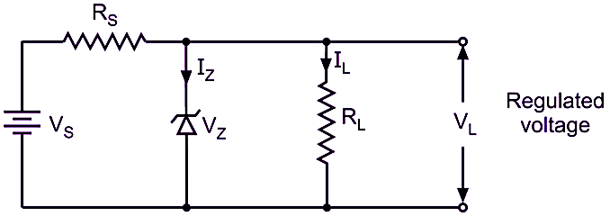
Figure 1. Zener Diode Voltage Regulator Circuit
Twelve volts is a standard voltage value for a Zener diode. This particular device can be selected from a tolerance range of 1$\%$–20$\%$. The power dissipation rating of the Zener diode will be made after the value of the series resistor ($R_{S}$) has been determined by calculation.
A series resistor must be selected that will permit the Zener diode to operate within its prescribed range. The value of $R_{S}$ is equal to the minimum value of the input voltage, $V_{in(min)}$, minus the Zener voltage ($V_{Z}$), divided by the maximum value of the load current, $I_{L(max)}$. The voltage difference between $V_{in}$ and $V_{Z}$ represents the voltage that will appear across the series resistor. This voltage value divided by the maximum load current, $I_{L(max)}$, equals the value of $R_{S}$. For our circuit, we, therefore, find the value of $R_{S}$ to be:
$$R_{S} = \frac{V_{in(min)} – V_{Z}}{I_{L(max)}} = \frac{15V – 12V}{0.04A} = 75\Omega$$
The wattage rating of the resistor must also be determined from the basic power formula:
$$P = I \times V$$
For this particular application, the wattage rating of the series resistor is determined from the values of the maximum load current, $I_{L(max)}$, and the series resistor voltage ($V_{RS}$):
$$P = I_{L(max)} \times V_{RS} = 0.04 A \times 3 V =0.012 W$$
Since resistors do not have a standard wattage value of 0.012 W, a value of 0.25 W, or 1/4 W, will be selected for use in this circuit. This resistor can withstand significantly more heat than the calculated value.
The power dissipation rating, or $P_{D}$, of the Zener diode is a calculated value. In this case, power dissipation is determined by the basic formula:
$$P_{D} = I_{Z} \times V_{Z}$$
The maximum $I_{Z}$ value of the formula is first determined by finding the total current ($I_{T}$) passing through $R_{S}$ and then subtracting the minimum load current $I_{L(min)}$ from $I_{T}$. The power dissipation rating of the Zener diode is thus:
$$P_{D} = V_{Z} \times \left[\frac{V_{in(max)} – V_{Z}}{R_{S}} – I_{L(min)}\right]$$
$$= 12\,V \times \left[\frac{20\,V – 12\,V}{75\,\Omega} – 0\,A\right] $$
$$= 12\,V \times \left[\frac{8\,V}{75\,\Omega}\right] $$
$$= 12V \times 0.1067A$$
$$=1.28 W$$
Zener diodes are not available with a $P_{D}$ rating of 1.28 W. Therefore, a 5-W Zener would be selected for this application. This particular Zener could withstand a great deal more current than the calculated value.
Our calculations of the Zener diode and series resistor of the regulator are based on the assumption that the value of $V_{Z}$ remains fairly constant under normal circuit applications. This is done to simplify the calculations. As a rule, this is a good practical assumption. If the actual value of $V_{Z}$ does change in the operation of a regulator, the Zener impedance ($Z_{Z}$) of the diode could be used to determine changes in $I_{Z}$ values. $Z_{Z}$ is generally given in the manufacturer’s specifications of a diode.
Zener Diode Voltage Regulator Design Example
Design a Zener diode voltage regulator that calls for a 10-V regulated output and for a load current that will range from 0 to 30 mA. The unregulated input varies from 15 to 20 V DC.
Solution
- Determine the value of the series resistor ($R_{S}$):
$$R_{S} = \frac{V_{in(min)} – V_{Z}}{I_{L(max)}} = \frac{15V – 10\,V}{0.03A} = 167 \Omega$$
- Determine the wattage rating needed for the series resistor:
$$P = I_{L(max)} \times V_{RS} = 0.03A \times 5V =0.015 W$$
- Since resistors do not have a standard wattage value of 0.015 W, a value of 0.25 W, or 1/4 W, will be selected for use in this circuit.
- Select a Zener diode that will regulate voltage at 10 V. Since 10 V is a standard Zener voltage rating, we will select a 10-V Zener diode for this application.
- Determine the power dissipation ($P_{D}$) rating for the Zener diode:
$$P_{D} = V_{Z} \times \left[\frac{V_{in(max)} – V_{Z}}{R_{S}} – I_{L(min)}\right]$$
$$= 10V \times \left[\frac{20V – 15\,V}{167\Omega} – 0 \right]$$
$$= 10V \times 0.030A = 0.3 W$$
- Since 0.3 W, or 300 mW, is not a standard $P_{D}$ rating, we will select a 10-V Zener diode with a 500-mW $P_{D}$ rating.
Therefore, a 167-$\Omega$ 1/4-W resistor and 10-V, 500-mW Zener diode will be used for the voltage regulator circuit.
Key Takeaways
Zener diode regulators provide a simple and reliable method to maintain a constant voltage across a load, regardless of fluctuations in supply voltage or load current.