Learn more about the fundamentals of Zener diode operation, explore its characteristics curve, and delve into its wide range of applications, including voltage regulation.
The Zener diode is a special type of diode that is designed to work in reverse bias and in the so-called Zener region of the diode characteristic curve. This region is after the reverse-biased voltage has exceeded the breakdown voltage (breakdown point).
How Does a Zener Diode Work?
If the reverse bias voltage is less than the breakdown voltage, or if the Zener diode is forward-biased, it acts as an ordinary diode. That is, in forward bias, it allows current, and in reverse bias, it blocks current. After this voltage has surpassed the breakdown point (in reverse bias), the diode falls in the Zener region, where it conducts without getting damaged. The current in this region is called avalanche current. For a Zener diode, it is also called Zener current.
As soon as the voltage decreases, the diode retains its non-conducting condition and gets back to its normal properties. This specific property of being operational in the reverse bias and with avalanche current is given to the Zener diode by rich doping of the semiconductor material.
Moreover, by controlling the amount of doping, the thickness of the depletion region in the PN junction and the breakdown voltage can be set to any value.
Zener current: Same as the avalanche current (the higher current after breakdown occurs in a semiconductor device) in a Zener diode.
Zener Diode Characteristics
Figure 1 shows the characteristic curve of a Zener diode, which is more or less similar to that of an ordinary diode.
The range after the Zener knee (breakdown voltage) until the rated voltage of a Zener diode is reached is called the Zener region.
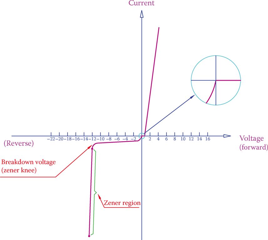
Figure 1 Zener Diode I-V Characteristics Curve
In this region, a small change in voltage leads to a large change in current. For instance, a change of 1 V in voltage can cause the current to increase by 10×.
Zener knee: a Sharp curve in the characteristic curve of a Zener diode where the breakdown voltage is reached and breakdown occurs.
Zener region: Region in the characteristic curve of a Zener diode where the breakdown has occurred because of the reverse voltage surpassing a certain value.
A Zener diode works when reverse biased. Otherwise, it behaves as an ordinary diode.
As can be understood from the characteristic curve, in this region, when the reverse voltage is smaller in absolute value than the Zener breakdown voltage, the current is very small and confined to the so-called leakage current, which is negligible and can be ignored.
But for higher reverse voltages, there is an abrupt and large increase in current. In other words, whereas the voltage remains almost constant, the current has a considerable variation. This is the significant property of a Zener diode, which can be employed.
- You May Also Read: Diode | Working Principle | Construction
A Zener diode has a different symbol to differentiate it from other diodes. This symbol is shown in Figure 2. The physical shape of a Zener diode can be the same as that of a regular diode.

Figure 2 Symbol for a Zener diode.
Zener Diode Specifications
Zener diodes are characterized by several specifications that define their operating parameters and performance. Common specifications for zener diodes include:
Zener Voltage (Vz): The breakdown voltage at which the zener diode starts conducting in the reverse-biased breakdown region. This ranges from 2.4V up to about 200V.
Zener Resistance (Zz): The change in voltage with respect to the change in current through the diode.
Power Dissipation (Pd): The maximum power that the zener diode can dissipate without getting damaged. Typical values include 400 mW, 500 mW, 1 W, and 5 W, while for surface mounted, 200 mW, 350 mW, 500 mW, and 1 W are typical.
Maximum Current (Iz): The maximum current that the zener diode can handle while maintaining its specified voltage regulation. This ranges anywhere between 200uA – 200A.
Temperature Coefficient (TC): The rate at which the zener voltage changes with temperature variations.
Reverse Leakage Current (Ir): The small amount of current that flows through the zener diode when it is reverse-biased below the zener voltage.
Breakdown Voltage Tolerance: The allowed variation in the zener voltage from its specified value.
These specifications help in selecting the appropriate zener diode for specific voltage regulation, current handling, and temperature stability requirements in various electronic circuits and applications.
Zener Diode as Voltage Regulator
The main application of a Zener diode is in voltage regulation.
Voltage regulation implies keeping a voltage at a desired value irrespective of current and other factors that tend to change it. It is very important for many devices to protect them from overvoltage (and excessive current, as a result).
The specific property of a Zener diode is that in its operating range, the voltage drop across it is constant (it has an internal self-regulatory characteristic). This could be understood from the characteristic curve in Figure 1, which can be expressed differently: a large current change in a Zener diode causes only a small variation in voltage. That is, the voltage drop across it is almost constant. In this respect, if a Zener diode is in parallel with another component, or device, the voltage across that device is kept constant, because of the Zener diode.
Voltage regulation: Controlling electric voltage in a circuit or a device to remain within the desired range (small variation) under different load conditions.
Figure 3 depicts a load in parallel with a Zener diode, both in series with the 200 Ω resistor R. Notice the polarity of the Zener diode.
The role of the resistor R is to provide the leverage for current adjustment. The Zener diode is a current governed device. If we remove R, the whole voltage is applied to the load.
Zener diodes come in different voltages, for example, 5.6, 7.5, 10, and 16 V, just to name a few. For each purpose, the right size diode (voltage and rated current) must be employed.
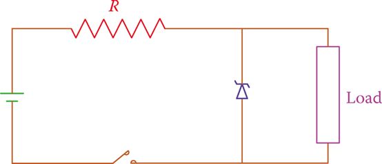
Figure 3 Zener diode in a circuit, regulating load voltage.
Zener Diode Application Examples
The following examples show the application of a Zener diode and the concerns for the proper rating. Note the polarity of the circuits in the reverse biasing of the Zener diode. If a Zener diode is used in forward bias, it performs as a regular diode.
In all the examples, there is a resistor in series with the Zener diode and the load. The Zener diode is in parallel with the load. When necessary, we refer to this resistor as the series resistor.
Example 1
In Figure 4 the 100 Ω resistor is the load and the diode used is a 4.7 V Zener diode. In each of the three cases, find the current in the load (note the polarity difference of the Zener diode in cases 2 and 3).
Solution
1. Following Ohm’s law, the current is
\[I=\frac{12}{150}=0.08A\]
The voltage drop in the 50 Ω resistor is (50)(0.08) = 4 V.
2. The Zener diode is forward-biased, and it behaves as a regular diode. The voltage drop across it is only 0.7 V.
Current in the load = 0.7 ÷ 100 = 0.007 A = 7 mA
Current in the 50 Ω resistor = (12 − 0.7) ÷ 50 = 0.226 A = 226 mA
Current in the diode = 226 − 7 = 219 mA
3. The Zener diode is reverse-biased and performs as a voltage regulator
Current in the load = 4.7 ÷ 100 = 0.047 A = 47 mA
Total circuit current = Current in the 50 Ω resistor = (12 − 4.7) ÷ 50 = 0.146 A = 146 mA
Current in the diode = 146 − 47 = 99 mA
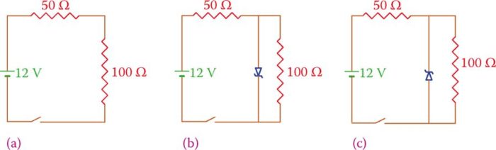
Figure 4 Example 1. (a) No Zener diode in the circuit. (b) The zener diode is forward-biased. (c) The zener diode is reverse-biased.
Example 2
If the value of the 50 Ω resistor in Example 1 is changed to 200 Ω, what is the change in the circuit current, in case 3 only?
Solution
The current in the 50 Ω resistor must always be greater than the load current because it is the sum of the current is the Zener diode and the load. If we calculate the currents in the load and in the 50 Ω resistor, we have
$\begin{align} & Load\text{ }Current=\frac{4.7}{100}=0.047A \\ & Current\text{ }in\text{ }the\text{ }50\Omega \text{ }Resistor=\left( 12-4.7 \right)\div 200=0.036A \\\end{align}$
But, we observe that this current is smaller than the load current; thus, this is not a possible case. A value of 200 Ω resistor is not acceptable.
Example 2 shows that in selecting a series resistor for inclusion in the circuit when a voltage regulator is used, care must be taken not to have an improper size resistor.
In such a case, the circuit does not function as desired. The action of a Zener diode is that it absorbs the extra current of the circuit that would flow through the load. But, in the case of Example 3, there is no extra current.
For the circuit just discussed, the current is 12 ÷ 300 = 0.04 A, and the Zener diode does not play any role.
When using a Zener diode, it is important to remember that:
1. The voltage across the load (in case the Zener diodes is removed) must be more than the Zener diode value for voltage regulation to happen.
2. The current in the series resistor (the total circuit current) must be higher than the load current.
3. We cannot entirely eliminate the series resistor.
For regulating the voltage across a load we cannot entirely eliminate the series resistor.
Zener Diodes in Series and Parallel
In the same way that diodes could be put in series if a larger regulated voltage is required a number of (compatible) Zener diodes can be put together in series. For example, in Figure 5, three Zener diodes are put together to provide a larger regulated voltage for the load.
Also, it is possible to put Zener diodes in parallel to increase the current capacity. Figure 6 depicts an example.
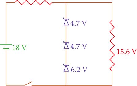
Figure 5 Zener diodes in series.
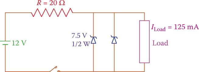
Figure 6 Zener diodes in parallel.
Key Takeaways
Zener diodes are designed to operate in the breakdown region and provide precise voltage regulation. By exploiting the phenomenon of avalanche breakdown, they offer a stable voltage reference and protection against voltage spikes, making them ideal for applications such as voltage regulation, voltage clamping, and voltage reference circuits.