The article discusses the hybrid parameters (h-parameters) used to analyze two-port networks, particularly circuits with active devices like transistors. It explains the determination of h-parameters through Thevenin and Norton equivalent circuits, covering short-circuit input impedance, open-circuit reverse voltage ratio, short-circuit forward current ratio, and open-circuit output admittance, with applications in transistor amplifier analysis.
What are H Parameters (Hybrid Parameters)?
Hybrid Parameters (H-parameters) are a set of four constants used to mathematically model linear two-port networks. These parameters express the relationship between the voltages and currents at the input and output terminals of the network. H-parameters are especially useful in the analysis of transistors and other electronic devices operating in the small-signal regime.
For analyzing circuits containing active devices such as transistors, it is more convenient to think of the input terminals of a four-terminal coupling network as a Thévenin-equivalent voltage source and the output terminals as a Norton-equivalent current source. We then describe the coupling network in terms of four hybrid parameters (h-parameters). We determine these parameters using the same measurement techniques as for z-parameters and y-parameters.
How to Find H Parameters of Two Port Networks
To find the open-circuit voltage of the Thévenin-equivalent source at input terminals (port 1) in Figure 1(a), we feed V2 into the output terminals (port 2). In this circuit, we consider the Thévenin-equivalent source to be a voltage-controlled voltage source. The parameter that represents the fraction of the output voltage appearing at the input terminals is V1/V2, which is a ratio without units. This parameter is the open-circuit reverse- voltage ratio, h12.
Since we are treating the dependent source as a voltage-controlled voltage source, we short-circuit the output terminals while we measure the input voltage and current, as shown in Figure 1(b). The parameter h11 is V1/I1, which is expressed in ohms and represents the short-circuit input impedance of the network. Since h12V2 is a voltage source, the equivalent input circuit for the coupling network shows the dependent voltage source and input impedance in series, as in Figure 1(c).
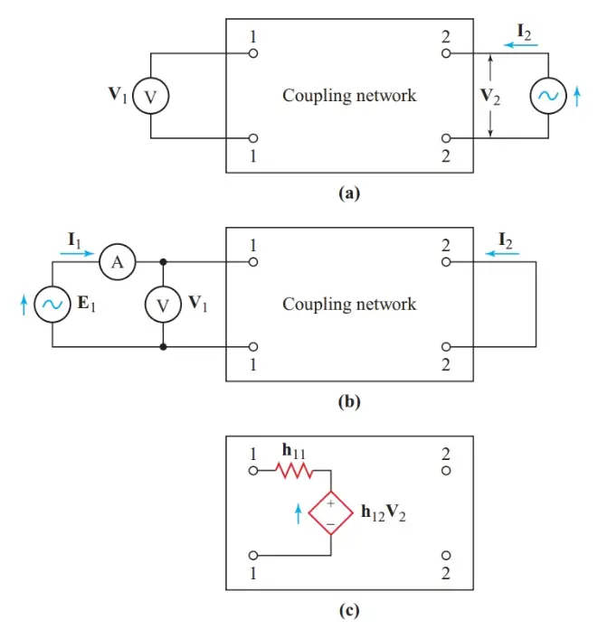
Figure 1 Finding the Thévenin-equivalent input circuit of a four-terminal network: (a) Open-circuit reverse voltage; (b) Internal input impedance; (c) Network input parameters
To determine the short-circuit current of the Norton-equivalent source at the output terminals (port 2) in Figure 2(a), we feed I1 into the input terminals and short-circuit the output terminals through the ammeter measuring I2. As long as the network impedances are linear (independent of voltage and current), I2 will be a constant fraction of the input current I1. The ratio I2/I1 is the short-circuit forward-current ratio, h21.
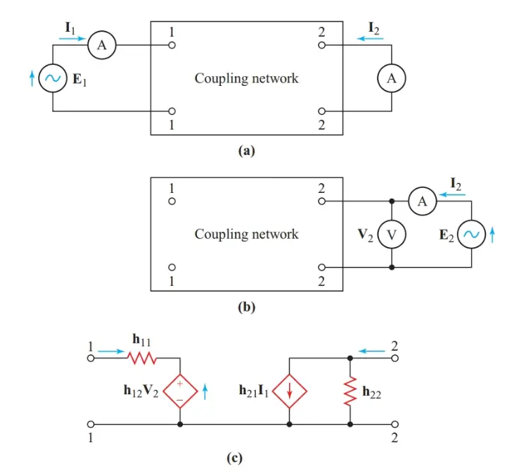
Figure 2 Finding the Norton-equivalent output circuit of a four-terminal network: (a) short-circuit forward current; (b) output admittance; (c) complete hybrid parameters.
The output impedance of a Norton-equivalent source is in parallel with the current source, so the fourth hybrid parameter is expressed as an admittance. Since we are treating this dependent source as a current-controlled current source, we leave the input terminals of the network open-circuit to make I1 zero while we measure I2 and V2. The parameter h22 is I2 /V2, which is expressed in Siemens and represents the open-circuit output admittance. These equations summarize the four hybrid parameters of a four-terminal coupling network:
Short-circuit input impedance:
\[\begin{matrix}{{\text{h}}_{\text{11}}}\text{=}\frac{{{\text{V}}_{\text{1}}}}{{{\text{I}}_{\text{1}}}}\left( \text{with }{{\text{V}}_{\text{2}}}\text{=0} \right) & {} & \left( 1 \right) \\\end{matrix}\]
Open-circuit reverse-voltage ratio:
\[\begin{matrix}{{\text{h}}_{\text{12}}}\text{=}\frac{{{\text{V}}_{\text{1}}}}{{{\text{V}}_{\text{2}}}}\left( \text{with }{{\text{I}}_{\text{1}}}\text{=0} \right)Open-Circuit & {} & \left( 2 \right) \\\end{matrix}\]
Short-circuit forward-current ratio:
\[\begin{matrix}{{\text{h}}_{\text{21}}}\text{=}\frac{{{\text{I}}_{\text{2}}}}{{{\text{I}}_{\text{1}}}}\left( \text{with }{{\text{V}}_{\text{2}}}\text{=0} \right)Short-Circuit & {} & \left( 3 \right) \\\end{matrix}\]
Open-circuit output admittance:
\[\begin{matrix}{{\text{h}}_{\text{22}}}\text{=}\frac{{{\text{I}}_{\text{2}}}}{{{\text{V}}_{\text{2}}}}\left( \text{with }{{\text{I}}_{\text{1}}}\text{=0} \right) & {} & \left( 4 \right) \\\end{matrix}\]
Figure 2(c) shows the resulting h-parameter equivalent circuit. For the Thévenin-equivalent source for the network input, we can write a Kirchhoff’s voltage-law equation, as we did for z-parameters. For the Norton-equivalent source for the network output, we write a Kirchhoff’s current-law equation, as we did for y-parameters. The two unknowns in these equations are I1 and V2.
$\begin{align}& \begin{matrix}{{\text{h}}_{\text{11}}}{{\text{I}}_{\text{1}}}\text{+}{{\text{h}}_{\text{12}}}{{\text{V}}_{\text{2}}}\text{=}{{\text{E}}_{\text{1}}} & {} & \left( 5 \right) \\\end{matrix} \\& \begin{matrix}{{\text{h}}_{\text{21}}}{{\text{I}}_{\text{1}}}\text{+}{{\text{h}}_{\text{22}}}{{\text{V}}_{\text{2}}}\text{=}{{\text{I}}_{\text{2}}} & {} & \left( 6 \right) \\\end{matrix} \\\end{align}$
The transistor amplifier equivalent circuit of Figure 3 is a typical example of hybrid parameters.
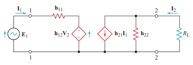
Figure 3 Hybrid (h) parameters of a simple transistor amplifier
We cannot use Thevenin’s theorem to find the equivalent internal resistance of a dependent source when the controlling element is included in the transformation. Therefore, when we want to determine the input and output impedances of coupling networks, we must calculate V/I. We determined h11 with a short circuit across the output terminals of the network. In the circuit of Figure 3, Zin differs slightly from h11 since the circuit has some reverse coupling.
Why Use H-Parameters?
- Particularly suited for modeling bipolar junction transistors (BJTs) in the common-emitter configuration.
- Easy to measure in practice because short-circuit and open-circuit tests are relatively simple.
- Allow cascading of two-port networks for system-level analysis.
Hybrid Parameters (H Parameters) Summary
$$\begin{aligned}
V_1 &= h_{11} I_1 + h_{12} V_2 \\
I_2 &= h_{21} I_1 + h_{22} V_2
\end{aligned}$$
| Parameter | Description | Condition |
|---|---|---|
| h₁₁ = V₁ / I₁ | Input impedance | V₂ = 0 (output short-circuited) |
| h₁₂ = V₁ / V₂ | Reverse voltage gain | I₁ = 0 (input open-circuited) |
| h₂₁ = I₂ / I₁ | Forward current gain | V₂ = 0 (output short-circuited) |
| h₂₂ = I₂ / V₂ | Output admittance | I₁ = 0 (input open-circuited) |
Hybrid Parameters (H Parameters) Key Takeaways
In conclusion, hybrid parameters (h-parameters) play a crucial role in analyzing and designing circuits involving active components like transistors. Their ability to describe the input and output characteristics of a network using simple measurements makes them invaluable in applications such as transistor amplifier design, where they help in determining gain, input and output impedances, and overall circuit stability. By leveraging Thevenin and Norton equivalents, h-parameters provide a systematic approach for evaluating complex electronic circuits, making them essential in fields like communication systems, signal processing, and electronic circuit design. Their practical significance extends to designing efficient amplifiers, ensuring reliable circuit performance, and facilitating easier integration of components in modern electronic devices.