The article explains the fundamental theory behind wound rotor and squirrel cage induction motors, focusing on their operating principles based on electromagnetic induction and the structural differences in their rotors. It highlights the economic and performance considerations that make squirrel cage motors more widely used, while also noting the specific advantages of wound rotor motors in certain applications like wind turbines.
Asynchronous machines are more known as induction motors because their principle of operation is based on induction. Recalling Faraday’s law, if a wire is moved in a magnetic field, then a voltage difference is generated between its two ends. We may also say a voltage or an electromotive force is induced in the wire.
Remember, also, that it is the relative motion between a wire and a magnetic field that counts; that is to say, the wire can be stationary while the magnetic field moves.
Asynchronous motor: Another name for an induction motor.
This principle, together with the rotating magnetic field, constitutes the basis for the operation of induction motors and generators. Hence, one can say the difference between synchronous and induction machines lies in their rotors.
In other words, it lies in how the magnetic field in the rotor is made. In this sense, the structure of the stator for a synchronous machine and an induction machine is the same, and only the rotors differ from each other.
That is to say, in principle, one can interchange the stators of two similar (in size and power) synchronous and induction motor
There are two types of induction motors. The difference again comes from the structure of the rotor, and the two types are named based on the rotor structure. One type is called Squirrel cage motor and the other is called wound rotor induction motor (WRIM).
The rotor of the squirrel cage motor has no winding, and there is no need for the rotor to be electrically connected to any electricity.
The rotor of the latter, however, as the name implies, has windings. The windings must be connected to circuits outside of the rotor, though not to the three voltage lines. The arrangement for windings on the rotor, which rotate, to be connected to outside circuitry that is stationary is done through slip rings.
Slip rings are metallic circular rings mounted and rotating with the rotor shaft and connected to the rotor windings but insulated from the rotor body.
Brushes are spring loaded to make good contact with the surface of the rings. They do not rotate and are connected to the outside circuitry.
Remember that in DC machines we had brushes and commutators. The difference between slip rings and commutators is that the former is made of one piece of metal, whereas the latter consists of many isolated pieces of metals around a ring.
In both cases, they are isolated from their shafts. Also, for DC machines, there is only one commutator, but for AC machines there are two (for single phase) or three (for three-phase) rings.
Squirrel cage induction motor: Type of alternating current induction motor in which the rotor winding has little resistance and thus carries very high current. To withstand high currents, the rotor structure is modified and more resembles a cage than a winding.
Wound rotor induction motor (WRIM): Type of induction motor for AC in which the rotor has wire winding. The windings are accessible through slip rings. Another type is (squirrel) cage motor that has no wire winding and has no slip rings.
Three-Phase Wound Rotor Induction Motor
Consider Figure 1 in which a one loop wire (for simplicity) is placed inside a rotating magnetic field.
Notice that the single wire loop is connected to a resistor and together they form a closed loop. Also, notice that the resistor is external to the wire loop and its connection to the wire loop is through slip rings that are mounted on the shaft holding the loop.
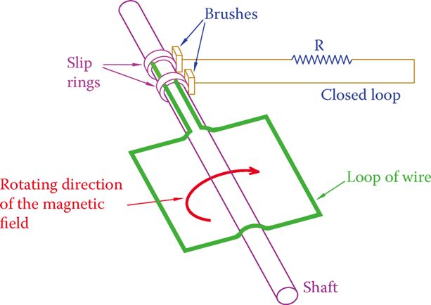
Figure 1 One loop of rotor winding connected to outside circuit through slip rings.
The loop ends are fixed to the slip rings, and two brushes make the connection between the slip rings and the external circuit.
Rotation of the stator magnetic field is equivalent to moving the wire in a stationary field. The following lines describe what happens as a result:
- Because the magnetic field is moving, it induces a voltage in the wire.
- Because the wire ends are connected to the resistor and form a closed circuit, a current is developed in the loop (including the resistor), proportional to the induced voltage.
- Because of the current in the loop, a force is generated that pushes each side of the loop wire in opposite directions, thus creating a torque. This torque makes the wire loop and its shaft rotate.
- This is what happens in a wound rotor AC induction motor. There is no connection to the electricity for the rotor winding (the loop wire), but the rotor windings make a closed circuit through the external resistor.
- We see that the torque develops if there is a current in the rotor windings. If there is no current, the torque diminishes. In other words, as long as there is a current in the rotor winding, motion exists. This current exists when there is a relative motion between the magnetic field and the rotor winding. If the rotor runs at the same speed as the magnetic field, then there is no relative motion. For this reason, to maintain current, in a motor the rotor always runs slower than the magnetic field.
- For simplicity and clarity, in Figure 1 and the above description, there was only one loop. Other loops at a different angle can be connected in parallel with the loop shown, using the same slip rings.
- One loop, or a few loops in parallel with each other (two connections), corresponds to a single-phase machine. But, the discussion is equally valid for three-phase machines, having three separate loops (or three sets of parallel loops). The winding in the rotor of a single-phase machine has two terminals that must be connected to the outside of the rotor through two slip-ring-brush sets. Three-phase rotor windings have three terminals and need three slip rings.
- The current flowing in the rotor winding cannot be direct current; thus, it has an AC nature at a certain frequency.
- The outside resistor can be used for various purposes (e.g., control of the current in the rotor winding when necessary). It can also modify the performance characteristic of a machine.
Normally, winding rotors is a costly job and the slip-rings-brush sets add to the cost and need repairs. For these reasons, the wound rotor induction motors are relatively costly. Their counterpart squirrel cage motors are much cheaper and economically preferred.
Squirrel Cage Induction Motor
Referring to Figure 1, suppose that the outside resistor is replaced by a piece of wire with no resistance. This immediately causes a significant increase in the current in the rotor windings.
To compensate for the higher current, a thickness of the wires in the rotor windings must accordingly be increased. In addition to the wire thickness increase, we observe that in such a case, then, there is no need for a set of slip rings because the external resistors do not exist anymore and, thus, the wire loops can be closed inside the rotor rather than outside the rotor. This latter reality has been the basis of the squirrel cage motors, in which the extra cost of the slip rings and brushes have been eliminated.
The windings of a squirrel cage motor are a number of thick bars of copper, brass, or aluminum (to carry very high currents) that are shorted together (forming parallel components) at both ends.
Because the metal bars are connected to two circular rings at their ends, connecting them together, they form a cage shape, as shown in Figure 2. The name “squirrel cage,” thus, stems from the shape of the conducting bars.
This is the simplest form of a cage, where the bars have a circular cross-section; they are parallel to each other and parallel to the rotor shaft.
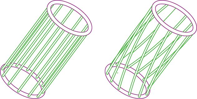
Figure 2 Cage structure of squirrel cage induction motor
The bars can be slanted (like a twisted cage) or they can have a different cross-section rather than being circular. These are variations of models of squirrel cage motors for various reasons or purposes.
The aluminum or copper cage is embedded in a ferrous material to increase the permeability of the rotor winding. The ferrous medium is laminated (like the metals in a transformer) to prevent or reduce eddy currents, thus reducing heat and losses. The cage, therefore, is not hollow.
A hollow rotor would have a much less efficient performance. The picture of a tiny squirrel cage motor, illustrating the squirrel cage rotor, is shown in Figure 3a. (This motor is one phase since it is so small.) A three-phase 1.5 hp squirrel motor is illustrated in Figure 3b.
Most of the motors used in industry are induction motors. Out of those, the majority are of the squirrel cage type. This is because of the obvious economic reason; as was mentioned earlier, beyond the initial higher cost, the wound rotor induction motors need maintenance work on their brush and slip rings, whereas the squirrel cage motor is relatively maintenance free. Hence, unless necessary for any technical reason, after a squirrel cage motor has acceptable performance, it will be the candidate for a job.
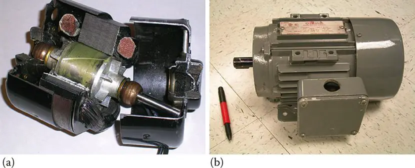
Figure 3 Squirrel cage induction motor: (a) very small single-phase motor and (b) 1.5 hp three-phase motor.
As a generator, one can say that almost the only application of induction generators is in wind turbines. The intrinsic performance of this machine matches well with the nature of wind, having a variable speed and not being in our control.
Formerly, almost all of the wind turbine generators were of squirrel cage type, but, gradually more and more wound rotor induction generators are being used because of their advantages in grasping more power from the wind, despite their extra cost. Their advantages outweigh the higher cost.
Wound Rotor & Squirrel Cage Induction Motor Key Takeaways
Understanding the fundamental differences between wound rotor and squirrel cage induction motors is essential due to their significant impact on industrial and renewable energy applications. Squirrel cage motors, with their cost-effectiveness, durability, and minimal maintenance needs, dominate general industrial use, powering everything from fans to conveyor belts. On the other hand, wound rotor motors, though more complex and expensive, provide critical benefits such as controlled starting torque and adjustable performance, making them ideal for high-inertia systems like cranes and wind turbines. Their ability to adapt to varying load conditions enables efficient energy extraction in wind energy generation.