The article provides an overview of synchronous generator, explaining their working principle, components like slip rings and exciters, and the two main types: rotating-armature and rotating-field generators. It also discusses their use in large-scale utility applications and wind turbines, highlighting advantages such as efficiency, constant frequency output, and minimal slip.
A synchronous generator is a machine that produces AC voltage when its shaft is rotated. A synchronous generator is called synchronous because the generated voltage waveform it produces is synchronized with the rotation of the generator.
What is a Synchronous Generator?
A synchronous generator is an ac generator in which the output is synchronized to the position of the rotor.
The frequency of the voltage produced by the synchronous generator depends only on the speed at which its shaft is turned and the number of poles it has. This makes the synchronous generator very efficient for producing electrical power for utility companies because it produces power at line frequency on a continual basis when its rotor is rotated at a constant rate.
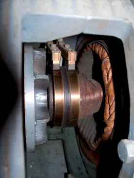
Figure 1 Slip Ring and Carbon Brushes Diagram
Slip rings are smooth rings that are mounted on a rotor and connected to one end of the rotor coil.
Brushes ride directly on the slip rings and make electrical contact with the external terminals. Brushes wear down eventually, so they must be inspected periodically and replaced as needed.
Large synchronous generators require an excitation voltage for the field. This voltage comes from a separate power source, such as a smaller auxiliary dc generator called an exciter, to supply field current.
Usually, the exciter is mounted on the main shaft. Different types of exciters include separate exciters that are dc generators, static exciters (with no rotating parts), and shaft-driven dc exciters. Current from the exciter is usually controlled by an automatic or manual regulator.
Synchronous Generator Types
You will encounter two types of AC synchronous generators when you are working with renewable energy systems.
In one type, the armature is the rotor, and current from the armature is generated in the rotor; this is called a rotating armature AC generator. In this case, slip rings and brushes are used to pass current from the rotor through insulated porcelain bushings to the electrical terminals on the frame of the generator.
The other type has the field on the rotor and the armature on the stator. In this case, slip rings and brushes may not be necessary because power is produced in the stationary stator, and rotor current can be supplied from a separate rotating exciter that is mounted on the same shaft. This is called a rotating-field AC generator.
In either case, the rotor shaft is connected to a prime mover that causes it to spin.
In large generators, the field rotates, and the armature windings are on the stator. Three-phase is standard for utilities because it can be transmitted at a lower cost, and a three-phase generator is significantly smaller than a single-phase generator of the same rating.
The electrical frequency of the three-phase output voltage depends on the mechanical speed of the rotor and the number of poles in the generator, as mentioned previously.
Rotating Armature AC Synchronous Generator Working
The rotating armature generator is also called the stationary field generator. In a small rotating-armature generator, the magnetic field can be supplied by permanent magnets surrounding the rotor or by electromagnets.
Because the armature is in the rotating assembly, slip rings and brushes are used to take current from the rotor and pass it to the output.
In addition to hundreds of windings, the practical rotating-armature generator usually has many pole-pairs in the stator that alternate as north and south poles around the periphery.
Opposite poles are positioned next to each other so that the rotor generates a complete sine wave as it passes each pair of poles.
When the prime mover turns the rotor, the armature windings cut the magnetic flux lines from the field and generate a sinusoidal wave.
The poles for the field winding are part of the magnetic path; the path includes the rotor, air gap, stator poles, and case, but not the bottom plate.
The bottom plate is made of a nonmagnetic material to eliminate induced current. The field windings are wound on the poles.
A single-phase generator has two slip rings that are connected to the coil on the rotor.
Rotating armature AC generators are typically used for low-power applications, usually less than 5 kVA because the current through the slip rings and brushes is low. Most rotating-armature generators produce only single-phase.
Rotating-Field AC Synchronous Generator Working
All large ac synchronous generators are rotating-field generators, which are universally used by utility companies. The rotating-field ac generator is also called the stationary armature generator.
Because the armature windings are on the stator, larger amounts of power can easily be generated and moved to the load or to the grid (there are no moving contacts between the armature and the output terminals).
In very small, rotating-field AC generators, permanent magnets may be used for the rotor field; however, most rotating-field generators use an electromagnet for the rotor (this is known as a wound rotor).
A wound rotor is a rotor core assembly that has a winding made up of individually insulated wires.
In a generator, dc is supplied to the rotor to provide the magnetic flux for the rotating field. Because dc is provided, the electromagnet has fixed polarity (like a bar magnet). As the rotating magnetic field sweeps by the stator windings, the magnetic field from the rotor cuts through armature windings in the stator, and power is generated.
Utility companies are particularly concerned about the efficiency of their generators. As generators are made larger, their efficiency improves.
A large machine actually weighs less per kW produced than a small machine, and with the increase in efficiency, a larger one is better from a utility company perspective.
The only drawback is that large generators require some form of cooling. Three basic cooling systems—air cooling, compressed hydrogen cooling, and water/oil cooling systems—are in use.
The required cooling system depends on the specific type of generator and power output. For example, large, low-speed, multi-pole generators are easier to cool than high-speed generators.
In a rotating-field AC generator, the current for the field winding is usually produced from an exciter.
As mentioned previously, several different types of exciters are available, but it is common for the exciter armature and the main field rotor to move together on a common shaft.
The exciter can be a dc generator or it can be an alternator that uses diodes to convert its output to dc. The net result is the required dc that is used to create the rotor field.
Figure 2 shows a diagram of a large rotating-field AC generator. It has a dc exciter generator on the left end of the rotor and a rotating field in the main generator.
The armature for the main generator is made of coils of wire pressed onto the stator poles. These coils are connected as three separate windings located 120° apart to produce three-phase (3φ) voltage.
The current in the rotating field is controlled by the exciter, which in turn controls the output. The output voltage from the AC exciter is a three-phase AC that is routed through a rotating six-diode bridge rectifier, where it is turned into dc.
Because the exciter armature and diodes are mounted on the same shaft as the field windings of the main generator, the two wires that provide positive and negative dc to the main generator field can be connected directly without the need for slip rings and brushes. This means that the generator can run long periods between maintenance times.
The field current can be controlled directly with a regulator, or the output voltage of the exciter can be controlled to increase or decrease the main generator output.
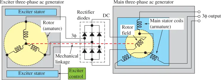
Figure 2 Diagram of Rotating-Field Synchronous Generator with an Exciter that Supplies Current for the Rotor Field
Figure 3 shows a large three-phase synchronous generator that can produce up to 75 MVA of power. This is an example of a rotating-field generator that uses an exciter to provide field current.
The rotor on the synchronous generator may be made as a salient pole or a nonsalient pole.
The term salient means projecting beyond a surface, level, or line. The salient poles consist of wires wrapped tightly around magnetic pole pieces that project from the rotor. This design is limited to lower-speed generators, so it is useful for some smaller wind turbines and some low-speed hydroelectric turbines.
Generators with nonsalient poles are used for higher speeds and are useful in fossil-fuel and nuclear plants, where they typically spin at 3,600 rpm to take advantage of the high-pressure steam.
The higher rotational speeds produce stronger centrifugal forces, which would pull salient pole rotors apart.
Non-salient poles are also called turbine poles. They can be made as long steel cylinders. The rotor is made by pressing windings into slots of a pole piece, and this design can withstand the higher speeds produced by steam turbines.
Three-Phase Synchronous Generator Working
Figure 4a shows a simplified three-phase generator. The rotating field is shown as a permanent magnet.
When the prime mover rotates the field past the three stator windings, a three-phase sine wave is produced. Figure 4b shows the three-phase output from the generator.
A sine wave is produced as the pole of the field winding is rotated past the armature winding in the stator. If the North Pole generates the positive half of the sine wave, the South Pole generates the negative half cycle.
Because the armature windings are mounted 120° apart in the stator, the sine waves are separated by 120°.
Most generators produce three-phase because it is more efficient. If the final output needs to be DC, three-phase is easy to convert to DC using diodes. The synchronous generator does not have a slip, so the output frequency is constant when the speed is held constant.

Figure 3 Diagram of a Synchronous Generator for a Utility

Figure 4 Three-Phase Rotating-Field Generator and Three-Phase Sine Wave. Figure 4b shows the output of the generator. For simplicity, the rotor in Figure 4a is shown as a permanent magnet.
Synchronous Generators Used in Wind Turbines
The synchronous generator is generally used in wind turbines when the generator is connected directly to the grid and does not use an inverter.
A primary advantage of synchronous generators for wind turbines is that they can receive a voltage from the grid and act as an electric motor if the blades are not turning.
If the wind speed is low, the generator can act as a motor to begin turning the blades. The voltage from the grid helps the motor come up to near-synchronous speed and starts the blades turning fast enough so that the wind can take over.
If the motor were not used to turn the blades during start-up, the wind turbine would not be able to start to harvest energy until wind speeds are higher.
As the wind begins to pick up and the blades begin to harvest energy, the voltage from the grid is automatically disconnected from the synchronous machine, and the wind turbine blades begin to turn the shaft fast enough that it is generating electricity. This transition occurs above a wind speed of approximately 6 mph.
Another advantage of using the synchronous generator in a wind turbine is that when dc is provided to its rotating-field coil, a very strong magnetic field is created, and the synchronous generator has almost no slip.
Thus, if the generator is connected correctly to the grid, its shaft runs near its design speed at all times, which ensures that it produces voltage with a frequency near its rated 60 Hz.
Figure 5 shows a synchronous generator used in a wind turbine.
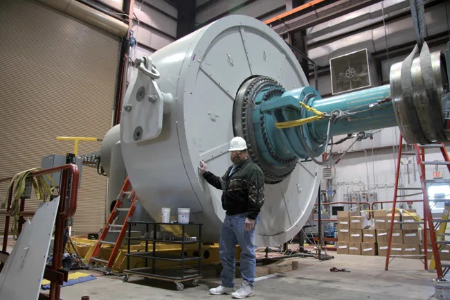
Figure 5 Diagram of a Generator for a Wind Turbine
How to Calculate the Speed of a Synchronous Generator?
The frequency of a synchronous generator is determined by the number of poles in the armature and the speed of the turning rotor. The equation for frequency from a synchronous generator is:
\[f=Np\times RPM\times 120\]
Where
f = frequency, in Hz
Np = number of poles
RPM = rotational speed, in revolutions per minute
Induced Voltage Frequency Calculation
What is the frequency of an induced voltage for a generator that has four poles and turns at 1,800 rpm?
Solution:
f=Np×RPM×120=4×1,800×120=60 Hz
Synchronous Generator Speed Calculation
How fast does a twenty-four-pole generator need to rotate to produce 60 Hz?
Solution
Table 1 summarizes the number of poles and rpm required to produce 50 Hz or 60 Hz, which are the two most common frequencies for electrical grids throughout the world.
The number of poles for a generator is always in pairs, so the number of poles is always an even number.
The higher the number of pole pairs, the lower the rotational speed for the generator to produce a given frequency.
| Number of Poles | RPM for 50 Hz | RPM for 60 Hz |
| 2 | 3,000 | 3,600 |
| 4 | 1,500 | 1,800 |
| 6 | 1,000 | 1,200 |
| 8 | 750 | 900 |
| 10 | 600 | 720 |
| 12 | 500 | 600 |
| 14 | 429 | 514 |
| 16 | 375 | 450 |
| 18 | 333 | 400 |
| 20 | 300 | 360 |
| 40 | 150 | 180 |
Table 1 Number of Poles Needed to Generate 50 Hz or 60 Hz
Figure 6 shows a second set of field poles on a generator. When the second set of poles is added, the output voltage of the generator has an extra sine wave for each revolution of the generator.
If additional poles are added, more sine waves are produced during each revolution of the rotor.
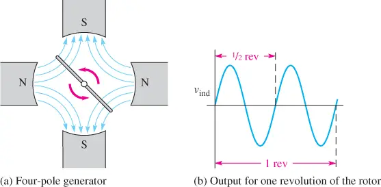
Figure 6 Output Sine Wave for a Generator with Four Field Poles. Notice that there are two cycles at the output for every revolution of the rotor.
Review Question
- What are the main parts of a synchronous generator?
- How does a rotating armature generator produce voltage?
- How does a rotating field generator produce voltage?
- How does a permanent magnet synchronous generator produce voltage?
Answers
- The main parts of a synchronous generator are the rotor (which generally is the field winding or, in small generators, a rotating permanent magnet, a method of supplying the field coils with electricity) and the stator (which is usually the armature where power is removed). Very large synchronous generators have an exciter that provides field current. If the exciter produces ac, there are diodes to rectify it for the required dc for the main generator’s field. Other generators have bearings, a cooling fan, and a case.
- In a rotating armature generator, the armature is a coil that cuts lines in the magnetic field provided by the stator and transmits the output through slip rings and brushes to the outside.
- In a rotating field generator, the field is provided by either a coil or a permanent magnet and provides a rotating field that generates a voltage in fixed stator coils as it spins. The output is taken from the stator windings.
- The permanent magnet provides the rotating magnetic field that induces a voltage in the stator coils as it passes them.
Synchronous Generator Key Takeaways
Synchronous generators play a critical role in modern power generation and distribution systems due to their ability to produce electricity at a constant frequency with high efficiency. Their precise synchronization between rotor speed and output frequency makes them ideal for large-scale utility applications, where maintaining a steady voltage and frequency is essential for grid stability. Whether used in fossil-fuel, nuclear, or renewable energy setups like wind turbines, synchronous generators offer reliable performance, minimal slip, and seamless integration with the power grid. Their diverse configurations—rotating-armature for smaller applications and rotating-field for high-power demands—allow for flexibility across a wide range of industries. These characteristics make synchronous generators not just important, but indispensable for ensuring consistent and scalable electrical power generation in today’s world.