This article covers different circuit breaker ratings (voltage rating, frequency rating, frame rating, continuous current rating, short circuit current rating, fuse rating, control voltage rating, and megavolt ampere rating, ) and its specifications. It also discusses circuit breaker nameplate details.
A circuit breaker is an electrical device that opens and closes a circuit by non-automatic means and automatically opens a circuit when a predetermined current overload is reached, without damage to itself. Circuit breakers protect circuits, and their function is similar to fuses.
A fuse is an electrical overcurrent protective device with a fusible portion that is heated and broken by the passage of excessive current.
The difference between circuit breakers and fuses is that circuit breakers can be reset and used repeatedly. In contrast, fuses must be replaced once they have been opened (blown) from an overcurrent condition.
An overcurrent protective device (OCPD) is a circuit breaker, fuse, or switch with an element that disconnects or discontinues current flow when the amount of current exceeds the design load. An OCPD is also known as a trip device.
Circuit breaker original equipment manufacturers (OEMs) design and build products with various ratings that must not be exceeded. Exceeding these ratings can cause catastrophic failure with resulting damage to nearby equipment as well as injury or death.
Circuit breaker ratings are determined by the National Electrical Manufacturer’s Association (NEMA) and the Institute of Electrical and Electronics Engineers.
NEMA is a trade organization that follows ANSI guidelines for the development of its standards. Usually, all members that develop and vote on a NEMA standard are OEMs.
The Institute of Electrical and Electronics Engineers (IEEE) is a professional association that is dedicated to advancing technological innovation and excellence of electrical and electronic equipment.
As defined in IEEE C37.100, a circuit breaker is “A mechanical switching device, capable of making, carrying, and breaking currents under normal circuit conditions and also, making and carrying for a specified time and breaking currents under specified abnormal circuit conditions such as those of short circuit.”
According to Article 100 of the NEC®, a circuit breaker is “A device designed to open and close a circuit by non-automatic means, and to open the circuit automatically on a predetermined overcurrent without damage to itself when properly applied within its rating.”
IEEE Standard C37.16 covers circuit breaker ratings, application, and operating conditions for low-voltage power circuit breakers.
Circuit breaker ratings, application, and operating conditions for high-voltage power circuit breakers are contained in IEEE Standard C37.04.
It should be noted that the NEC® definition states that a circuit breaker will open a circuit “without damage to itself when properly applied within its rating.” Consequently, a circuit breaker could fail if it is applied outside of its rating. Therefore, it is important to ensure that circuit breakers are properly applied within their ratings as specified on the nameplate located on the circuit breaker.
A nameplate is a metal plate attached to a device, such as a circuit breaker, that lists its technical specifications. See Figure 1. The circuit breaker ratings most commonly referred to are voltage, frequency, frame, continuous current, short-time current, short-circuit current, fuse, control voltage, and megavolt ampere (MVA) ratings.
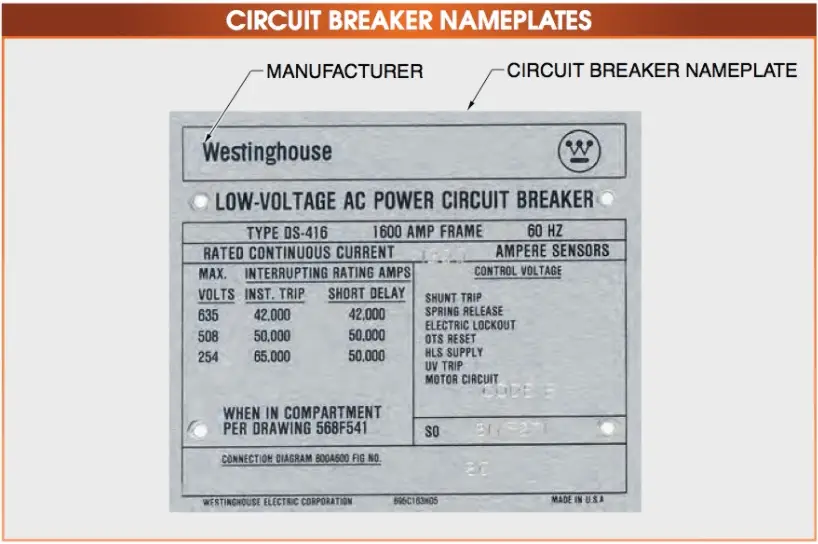
Figure 1. It is important to ensure that circuit breakers are properly applied within their ratings as specified on the circuit breaker nameplate.
Voltage Rating
According to IEEE Standard C37.13, “The rated maximum voltage of a circuit breaker is the highest RMS voltage, three-phase or single-phase, at which it is designed to perform. The circuit breaker shall be rated at one or more of the following maximum voltages: 635 V, 508 V, or 254 V. For fused circuit breakers, the 635 V rated maximum voltage becomes 600 V to match the fuse rating.”
The voltage rating of a circuit breaker is the maximum continuous voltage that can be applied to the circuit breaker without causing a dielectric failure of its insulation. Often a circuit breaker has more than one voltage listed on its nameplate. The actual voltage rating of the circuit breaker is the highest voltage listed on the nameplate.
TECH TIP
Maximum DC Voltage ratings are often less than the AC ratings. Circuit breaker poles in series are usually required in order to obtain the published DC ratings.
Frequency Rating
According to IEEE Standard C37.13, “The rated frequency of a circuit breaker is the frequency at which it is designed to perform. The standard frequency is 60 Hz. Application at other frequencies should receive special consideration”.
Circuit breakers are typically rated at 50 Hz or 60 Hz and are sometimes rated for use in direct current (DC) systems. One special consideration for using circuit breakers at other frequencies is that the continuous current rating of 60 Hz circuit breakers applied to DC systems is often decreased, sometimes by as much as 20%. This is due to DC being more difficult to interrupt than alternating current (AC) during short-circuit conditions.
Frame Rating
The frame rating is the continuous current rating of all current-carrying parts of a low-voltage circuit breaker, excluding its OCPD. This includes the primary disconnects or stabs, contact assemblies, and any other parts that carry current.
The OCPD, also known as a trip unit, is not included because it may have a rating lower than the frame rating of the circuit breaker. When the rating of the OCPD is less than the frame rating, it becomes the continuous current rating of the circuit breaker. For example, many electrical drawings show low-voltage circuit breakers rated as “1600 A-Frame” and “800 A Trip.” This type of rating indicates that the current-carrying components of a circuit breaker can carry up to 1600 A of current continuously but that the OCPD will operate whenever the current through it exceeds 800 A.
Continuous Current Rating
According to IEEE Standard C37.13, “The rated continuous current of a circuit breaker is the designated limit of RMS current at a rated frequency that it shall be required to carry continuously without exceeding the temperature limitations.
The preferred continuous current ratings of the various frame sizes are listed in ANSI C37.16. The rated continuous current of a circuit breaker equipped with direct-acting trip devices or fuses of a lower rating than the frame size of the circuit breaker is determined by the rating of those devices.”
Another way to define continuous current is that it is the amount of current a device can carry without exceeding its rated temperature rise over a set period of time. As current flows through a conductor, it creates heat. This is often referred to as copper loss (I2R).
As current flow through a conductor increases, the heat generated by copper loss also increases. At some point, the heat created by the current flow can be enough to cause thermal damage to the surrounding insulation. Most electrical devices have a rated temperature rise of 40°C (104°F) that is based on the thermal characteristics of the device insulation.
The methodology used in evaluating the electrical insulation thermal characteristics can be referenced in IEEE Standard 1, Section 7, IEEE Recommended Practice—General Principles for Temperature Limits in the Rating of Electrical Equipment and for the Evaluation of Electrical Insulation.
The rated temperature rise is the temperature rise of an electrical device or component above ambient, or surrounding air, temperature. For example, if the temperature of a device is 65°C (149°F) and the ambient temperature is 30°C (86°F), the temperature rise would be 35°C. Using this basis excludes the effects of ambient temperature and focuses on the actual temperature of the device or component. The second sentence in this definition refers to the “preferred continuous current ratings”.
IEEE Standard C37.16, Low-Voltage Power Circuit Breakers and AC Power Circuit Protectors — Preferred Ratings, Related Requirements, and Application Recommendations, provides recommended combinations of circuit breaker frame size, OCPD ratings, and voltage ratings. The third sentence of the standard is true for all circuit breakers, not just direct-acting OCPDs or fuses. “The rated continuous current of a circuit breaker equipped with direct-acting trip devices or fuses of a lower rating than the frame size of the circuit breaker is determined by the rating of those devices.” A direct-acting OCPD is also referred to by the IEEE as an electromechanical or series OCPD. Most series OCPDs were of an oil dashpot design, although Westinghouse manufactured an air dashpot device. These direct-acting OCPDs were connected in series with the load current. When they operated, they physically caused the circuit breaker to open by operating the trip bar. As with circuit breakers, series OCPD ratings can be identified by their nameplates. See Figure 2.
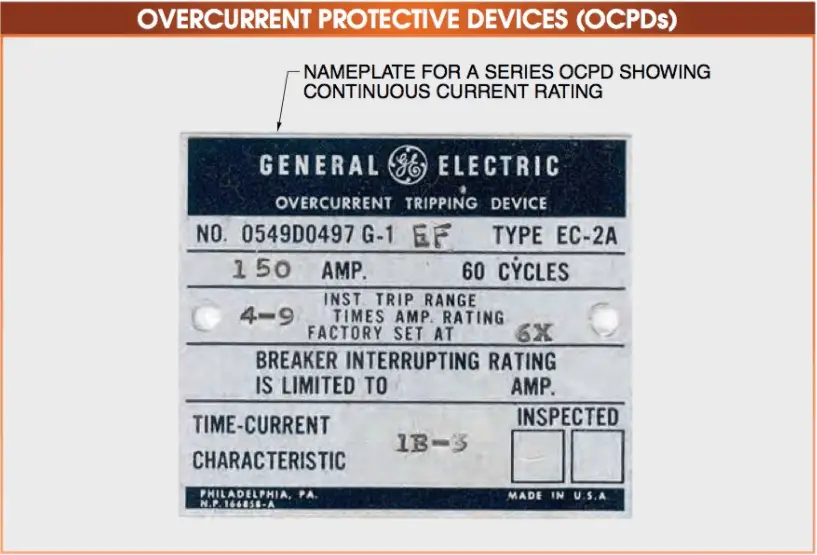
Figure 2. An OCPD (trip device) can be identified by its nameplate.
The actual continuous current rating of a low-voltage circuit breaker is always determined by the rating of its OCPD. The continuous current rating cannot exceed the frame rating of the circuit breaker but can be equal to it for a low-voltage power circuit breaker.
For example, a Westinghouse/Cutler- Hammer DS circuit breaker may have a 2000 A-frame rating while the OCPD may only have a rating of 1200 A. A molded-case circuit breaker can have a continuous current rating that is only 80% of its frame rating. Molded-case circuit breakers are typically smaller than other types of circuit breakers and have enclosed cases. This construction limits the amount of airflow through them.
The DS-style circuit breaker used in this example has a solid-state OCPD and uses current sensors to set the continuous current rating. This allows one circuit breaker to have several continuous current ratings by setting the taps on the current sensor to the appropriate value. Current sensors can be single-tap or multiple taps, depending on how the circuit breaker is ordered.
Note: An ITE K1600 circuit breaker with a 1600 A-frame rating could have either an electronic OCPD or a series OCPD (OD-3, OD-4, or OD-5). With a series OCPD, the continuous current rating would be determined by the coil rating of the OCPD. For the example 1600 A-frame ITE circuit breaker, ITE listed coil ratings from 300 A to 1600 A. Unlike the electronic OCPD, which may have several continuous current ratings by using a multi-tap sensor, the series OCPD would only have the one rating based on its coil rating.
IEEE Standard C37.06.5.3.1 provides the following conditions on which continuous current ratings are based:
- Circuit breakers are used under usual service conditions.
- The total temperature limits of the materials used for circuit breaker parts shall be considered. A temperature rise reference is given to permit testing at reduced ambient temperature. • Circuit breakers designed for installation in enclosures shall meet these ratings when in their proper enclosure and based on 40°C ambient temperature outside the enclosure.
- Outdoor circuit breakers and indoor circuit breakers without enclosures shall have ratings based on 40°C ambient temperature.
Most series-type OCPDs have a range of minimum pickup settings from 80% to 160% of the continuous current rating. Newer solid-state and digital OCPDs can have minimum pickup settings that range from 50% to 120%. Settings above 100% of the continuous current rating do not increase the amount of current the device can safely carry but are used to compensate for transient overcurrent conditions. For example, an electric motor that has an extra-long startup time could cause a circuit breaker set at 100% to a false trip. By increasing the minimum pickup to 140%, the motor would be able to start as designed. The primary problem with this easy fix is that the OCPD acts as if it has a higher continuous current rating than it actually does.
SAFETY TIP
Never set series-type OCPDs above 100% of their maximum continuous current rating without having an engineer review effects on the electrical power systems.
Short-Time Current Ratings
The short-time current rating of a circuit breaker is the maximum current it can safely carry for two 0.5 sec periods, with a 15 sec rest period between them at zero current.
According to IEEE Standard C37.13, “For an unfused circuit breaker, the rated short-time current is the designated limit of available (prospective) current at which it shall be required to perform its short-time current duty cycle (two periods of 1⁄2 s current flow, separated by a 15 s interval of zero current) at rated maximum voltage under the prescribed test conditions. This current is expressed as the RMS symmetrical value of current measured from the available current wave envelope at a time 1⁄2 cycle after short-circuits initiation.”
Note: Current-limiting fuses do not have a rated short-time current. Only the circuit breaker element of the fused circuit breaker assembly can have such a rating.
Electrical equipment is provided with overcurrent protection to protect it from high currents caused by overloads and short circuits.
Short-Circuit Current Ratings
According to IEEE Standard C37, “The rated short-circuit current of an unfused circuit breaker is the designated limit of available (prospective) current at which it shall be required to perform its short-circuit current duty cycle (0 – 15 s – CO) at the rated maximum voltage under the prescribed test conditions. This current is expressed as the RMS symmetrical value of current measured from the available current wave envelope at a time 1/2 cycle after short-circuit initiation. Unfused circuit breakers shall be capable of performing the short- circuit current duty cycle with all degrees of current asymmetry produced by three-phase or single-phase circuits having a short-circuit power factor of 15% or greater (X/R ratio of 6.6 or less).”
The short-circuit current rating, also known as the interrupting rating, is the maximum short-circuit current a circuit breaker can safely clear without external damage. External damage is specified since there will probably be some internal damage, such as erosion of the arcing contacts, carbon and other arcing by-products scattered inside the arc chutes, and thermal damage to the insulation system, due to the extremely high temperatures of the arc interruption process. However, there will be no external damage, and the circuit breaker should still be serviceable. The circuit breaker should be inspected after an arc interruption.
According to IEEE Standard C37.13, “Unfused circuit breakers with direct-acting instantaneous phase trip elements shall have short-circuit current ratings at each rated maximum voltage.” It is common for OEMs to state the short-circuit current ratings of their OCPDs at standard system voltage levels. See Figure 3. As the system voltage increases and the arc becomes more persistent and difficult to extinguish, the rating often has to be decreased.
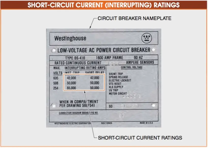
Figure 3. The short-circuit current rating is the maximum short-circuit current a circuit breaker can safely clear without being damaged externally. It is usually listed on the circuit breaker nameplate.
Fuse Ratings
Certain types of circuit breakers are protected by current-limiting fuses. A circuit breaker that uses current-limiting fuses will not have an interrupting rating but will use the interrupting rating of the fuse. By standard, current-limiting fuses must operate in half a cycle or less, although most fuse OEMs state that their fuses typically operate in a quarter of a cycle.
According to IEEE Standard C37.13, “The rated short-circuit current of a fused circuit breaker is the designated limit of available (prospective) current at which it shall be required to perform its short-circuit current duty cycle at the rated maximum voltage under the prescribed test conditions. The short-circuit current duty cycle consists of an O (OPEN) followed by a CO (CLOSE – OPEN) operation. The time between the O and CO operations is the time necessary to replace fuses and to reset the open-fuse trip device. This current is expressed as the rms symmetrical value of current measured from the available current wave envelope at a time 1⁄2 cycle after short-circuiting initiation.
Fused circuit breakers shall be capable of performing the short-circuit current duty cycle with all degrees of current asymmetry produced by three-phase or single-phase circuits having a short-circuit power factor of 20% or greater (X/R ratio of 4.9 or less).”
Control Voltage Ratings
According to IEEE Standard C37.13, “The rated control voltage is the voltage at which the mechanism of the circuit breaker is designed to operate when measured at the control power terminals of the operating mechanism with the highest operating current flowing. Rated control voltages and their ranges for low-voltage power circuit breakers are listed in Table 23 of ANSI C37.16.”
Coils, latches, motors, and other electrical components used to control a circuit breaker use lower voltage for the control circuit operation, most often DC voltage. Typical control voltages are 24 VDC, 48 VDC, 125 VDC, and 250 VDC. Less frequently, 120 VAC, 240 VAC, and 460 VAC are used. Some circuit breakers may have both AC and DC voltages of different nominal ratings. Control power will be brought into the circuit breaker through the secondary disconnects.
Megavolt Ampere Ratings
The short-circuit capability of oil, gas, and some older models of air circuit breakers is rated in megavolt amperes rather than or in addition to short-circuit current. A megavolt ampere (MVA) rating is the rated voltage times the rated interrupting current of a circuit breaker. Common examples are circuit breakers rated 250 MVA, 500 MVA, and 1500 A. MVA ratings for circuit breakers can be located in OEM manuals or on the nameplates. See Figure 4.
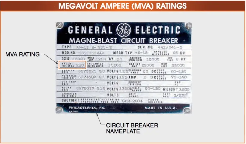
Figure 4. The short-circuit capability of some types of circuit breakers is rated in megavolt amperes (MVA) rather than in short-circuit current.