The article covers the essential protection devices used in electric motor circuits, focusing on methods to safeguard motors from overloads, fault currents, under-voltage, and over-temperature conditions. It outlines various protective components such as fuses, circuit breakers, over-current relays, thermal overloads, and temperature-dependent resistors, emphasizing their functions and integration in motor control systems.
Generally, the circuits supplying electric motors should be protected against overload and fault currents. In addition, any unattended motor should be protected against:
- Overloads
- Fault Currents
- Under-Voltage
- Over-Temperature.
There is also the requirement that all electric motors must have a control device for stopping and starting and an isolator.
All of the above requirements are usually met by installing fuses or circuit breakers in the switchboard, an electric motor starter with controls at a convenient location and an isolator near the electric motor. Modern proprietary motor starters are available with any, or all, of the above requirements built into the one unit.
Fuses
The fuse is possibly the simplest form of circuit protection. It consists of a fuse element designed to melt and prevent further current flow. The major disadvantage of a blown fuse is that the active component has to be replaced.
The primary purpose of a fuse is to protect a circuit rather than any load. Under short-circuit conditions the reaction time of an HRC fuse in isolating a circuit is probably the fastest of all protection systems.
A fuse element has to have a current rating high enough to allow an electric motor to draw starting currents, yet low enough to give some protection against overloads. Because of these opposing factors, a fuse cannot provide complete protection for both the circuit and the load.
Figure 1 shows a set of three typical HRC fuses used for electric motor circuit protection. They have a plastic carrier and base and are designed to be used with enclosed fuse links. HRC fuses are extremely consistent and reliable in terms of tripping values.
The element of an HRC fuse is enclosed in an insulating tube filled with powdered quartz to quench any arc that might develop.
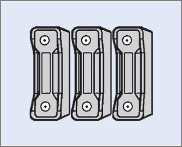
Figure 1 HRC fuses for three-phase electric motor circuit
Figure 2 shows a cutaway drawing of an enclosed type fuse link. This type has lugs to allow the fuse link to be held in place with machine-threaded screws. HRC fuses up to 63 A are often manufactured with plug-in fuse links.
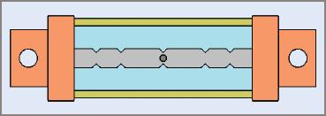
Figure 2 Cutaway view of a cartridge for an HRC fuse
The silver element has restrictions cut into its section in order to give a very fast response to fault currents. If a fault current flows through the fuse, the restricted sections of the fuse element heat up very quickly by the Joule’s law effect (H = I2Rt). This gives the HRC fuse a very fast response time to fault currents.
The fuse element of an HRC fuse has a eutectic bead to give a good response to prolonged overload currents. If a prolonged overload current flows, the eutectic bead will reach a point where it can no longer dissipate the heat and will melt. By careful selection of the mass of the eutectic bead, manufacturers can tailor the operation of the fuse to any time/overload-current characteristic required.
To ensure the safe operation of equipment, it is essential that only the correct size be used when replacing HRC fuses. Replacement cartridges of the correct size should be kept on hand for all HRC fuses.
When used to protect induction motor circuits, HRC fuses that are rated ‘M’ for motor starting should be used. These are capable of providing protection while not tripping on motor-starting currents.
Circuit Breakers
When circuit breakers are used for electric motor protection, the correct type must be used. Figure 3 shows a typical time/current characteristic of a type ‘C’ and ‘D’ circuit breaker.
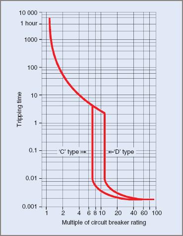
Figure 3 Typical time/current characteristic for ‘C’ and ‘D’ type circuit breakers
In can be seen from the characteristics that a standard ‘C’ type circuit breaker has the magnetic trip portion set at approximately 7.5 times the nominal current rating of the breaker. This value may not be enough to allow for the starting current of the motor and could result in nuisance tripping.
A ‘D’ type circuit breaker has the magnetic trip set to about 12.5 times the nominal circuit breaker rating. Note that tripping times that lie within the thermal characteristics are identical, as both types will trip at the same time for a steady overload.
The circuit breaker shown in Figure 4 combines the features of an electric motor circuit breaker and an isolator in the one unit.
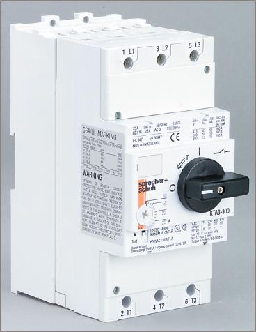
Figure 4 Combined electric motor circuit breaker and isolator
Over-Current Relays
Magnetically Activated Over-Current Relays
Instant tripping relays are operated by the direct action of the electric motor current on an armature. The principle is illustrated in Figure 5.
The relay consists of a series coil wound on a magnetic core. The coil is connected in one motor line and the armature is attracted to the main body of the core when the electric motor current exceeds a predetermined value.
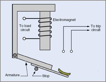
Figure 5 Simple electromagnetic overload trip
The mechanical movement of the armature can be arranged to either close or open an electrical circuit as desired.
Magnetic Trip Circuit Breakers with Dashpots
One construction method for an over-current relay is that of a coil wound on a cylinder. The coil is connected in series with the electric motor so it carries the same current as the motor.
A plunger positioned so that it can be attracted into the coil activates the tripping process when the motor current exceeds the preset value.
The direct-acting over-current relay has one serious disadvantage for protecting electric motors. Starting currents far exceed normal full-load running currents and the relay would trip out each time an attempt was made to start the electric motor.
Delayed Tripping
Time-delayed tripping is achieved by attaching a small oil dashpot to the plunger (see Figure 6). The piston has a small hole drilled in it and when excess currents attempt to pull the plunger into the solenoid, the action of the oil moving through the small hole delays the tripping action sufficiently to prevent operation while the starting sequence is occurring.
When correctly adjusted, the relay will not trip on starting current but will trip on even small sustained overloads.
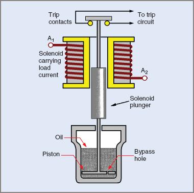
Figure 6 Magnetic overload with oil dashpot for time-lag
Thermal Overloads
Many types of thermal overload relays are available for electric motor protection. Some operate on different principles to others but all types are designed to open a contact when a temperature-sensitive element, such as a bimetal strip, receives sufficient heat to activate it.
Because the contact is usually connected in the control circuit of the starter, the opening of the contact allows the main contactors to drop out and switch off the supply to the electric motor.
The operating principle of most thermal overload elements relies on a bimetal strip (see Figure 7). Correctly designed thermal elements produce an amount of heat related to the amount of motor current.
The quantity of heat stored, and hence the temperature of the bimetal strip, relates to the amount of bending of the strip. After small short-duration overloads the heat can dissipate and the temperature of the strip is reduced. If small overloads continue for any length of time, the amount of heat generated will activate the relay.
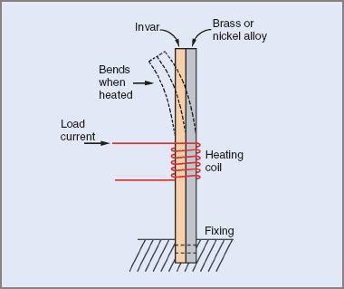
Figure 7 Operating principle of a bimetal strip
With starting currents, insufficient heat energy is developed in the strip for it to bend enough in the time taken for the motor to run up to speed and the current to reduce to the normal running value.
Ideally, there should be a thermal detecting element in each line of a three-phase electric motor but the trend is to use only two. In economic terms, the extra cost involved is small to that involved in replacing a partially burnt-out an electric motor.
Thermal overload elements are placed in the main supply lines leading to the motor, while the associated control contacts are connected in series with the control circuit. This is to ensure that if only one overload operates, it disconnects the electric motor from the supply.
Combined Thermal-Magnetic Over-Current Relays
In the thermal-magnetic version of the over-current relay, the advantage of the inbuilt delay of the thermal type is combined with the instantaneous tripping characteristic of the magnetic current overload relay.
The combination of the two methods is considered ideal electric motor protection.
- For very high currents, the magnetic section of the relay acts almost instantaneously.
- For small overloads, the heat accumulated in the thermal section causes delayed tripping according to the rate of heat generation.
Depending on design and application, the combined unit might not have oil dashpots to delay the magnetic relay action. Instead, it is set at a current rating in excess of motor starting requirements and the thermal element rating is retained at the lower value.
The combined unit shown in Figure 8 overleaf has three separate devices connected in series to fulfil a number of requirements. The components have been designed to operate together. The top part is a magnetically operated circuit breaker and isolator, the middle part is a contactor and the lower part is a thermal overload sensing unit.
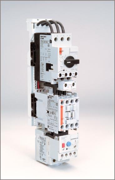
Figure 8 Electric Motor circuit breaker with contactor and overload unit
Figure 9 overleaf shows a small DOL starter. The contactor and overload unit can be seen mounted inside the starter, while the stop and start button are on the cover. This type has an IP65 rating.
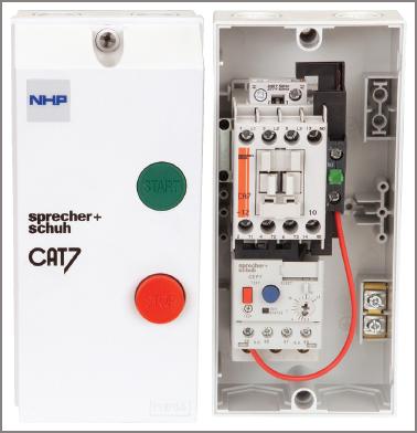
Figure 9 Small DOL starter with cover removed
Microtherm Devices
Temperature-Dependent Resistor Protection
A resistor with a positive temperature coefficient (PTC) has the characteristic of increasing its resistance only gradually until a critical temperature is reached. Above this point, its resistance increases rapidly. A popular trade name for this type of resistor is thermistor, although other names do exist.
This critical temperature can be varied by altering the composition of the material from which it is made. The determination of a critical temperature for a PTC resistor can also determine its use (see Figure 10).
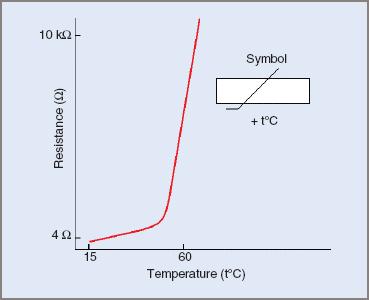
Figure 10 Typical PTC thermistor characteristic
For example, many electric motors are designed to have a maximum operating temperature of 60°C. At this temperature, the heat generated by motor losses is approximately equal to the heat being lost by the motor. Effectively this means that the temperature of the motor then remains constant.
PTC resistors are made in many different shapes so they can fit the requirement of particular jobs. When suitably insulated and placed inside the windings of a motor, the internal temperature of the windings can be monitored.
If the critical temperature is, say, 65°C, then the PTC’s resistance would increase rapidly above this temperature and can be an indication that there might be something wrong with either the electric motor or its load.
Temperature-dependent resistors, under normal conditions, are only capable of handling small values of current and must be used in conjunction with other equipment.
Figure 11 illustrates one method of monitoring the temperature of electric motor windings. During the winding process, a PTC resistor is inserted into each phase winding of the motor and all are connected in series with the coil of a small relay. This relay controls a pair of contacts in the control circuit of the electric motor starter. An isolating transformer and a bridge rectifier supply this circuit with direct current.
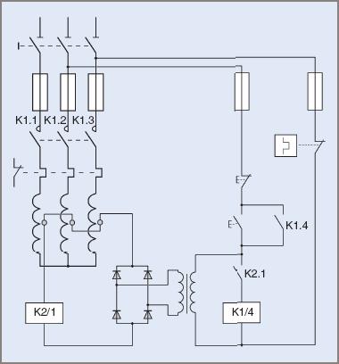
Figure 11 Using PTC resistors to protect electric motor windings
When the start button is pressed, the transformer supplies power to the PTC resistor circuit and, provided their collective resistance is below the critical temperature value, enough current will flow to activate the relay coil and close the contact connected in series with the main contactor coil.
Normal DOL starting procedure follows, with normal contactor action. If the temperature of any one of the three PTC resistors rises above the critical value, the resistance of the circuit increases, the current flow through the relay coil decreases, and the relay drops out. This action causes the main contactor to drop out and isolate the electric motor.
The complete control circuitry for of a thermistor relay is usually housed in the one unit (see Figure 12).
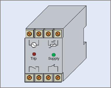
Figure 12 Typical thermistor relay
In a manner similar to other thermally activated devices, there is an inherent delay in a PTC resistor cooling down and resetting itself. A thermal overload is normally made as small as possible to reduce its thermal capacity but this has no effect on the thermistor when it is buried within the windings because they regulate the rate of cooling.
For a locked rotor situation, PTC resistors are an inadequate form of electric motor protection and external thermal and magnetic overload protection should still be provided.
The time taken for an electric motor windings to heat up when the rotor is locked in a standstill position is comparatively long and irreversible damage can be done to the motor windings before the PTC resistor exceeds its critical temperature and disconnection occurs.
Single-Phasing Protection
A three-phase electric motor operating under ideal conditions will draw three equal phase currents. This implies that the three line voltages are also equal; a situation that rarely exists in practice. A small variation in voltage of, say, 2 per cent can cause a current variation of about 10 to 15 per cent.
The function of an overload relay, whether magnetically or thermally activated, is to disconnect the electric motor from the supply lines under specified conditions of current flow and within a set period of time.
Overload relays are incapable of protecting an electric motor against internal faults, nor is that their intended function. Controllers are intended to handle the starting currents of induction motors. Fault currents may be many times this value so fuses or circuit breakers should be installed ahead of the controller.
The only protection readily available for a three-phase electric motor is the provision of thermal overload heating elements in each phase. An internal fault in the motor shows externally as greatly unbalanced line currents. Thermal or magnetic overloads can then disconnect the motor from the supply.
If an external fault occurs, such as a line to the motor becoming open-circuited when the electric motor is running, the motor is also said to be ‘single phasing’ and the two remaining line currents increase by approximately 73 per cent each. One of the phase windings then carries about twice as much current as the other two and motor damage can occur.
For smaller electric motors, the cost of installing phase-failure relays might be prohibitive but for larger motors it can be worthwhile as additional protection.
Voltage-sensitive relays are connected across each phase with operating contacts connected in the electric motor’s control circuit to ensure the motor is disconnected from the supply in the event of any phase voltage deviating outside specified limits.
Reverse-Phase Sequence Protection
Some machines can be damaged if inadvertently driven in the wrong direction by the drive motor. This can occur when the phase sequence of the supply has been changed.
A phase-sensitive relay is supplied by voltages from each phase and isolates the motor from the supply if the phase sequence is incorrect. The relay itself may be partially mechanical and operate a vane, which in turn operates contacts in the main control circuit, or it may be an electronic device.
Electronic Overloads
The modern equivalent of the thermal overload unit is the electronic overload. These units, which are of similar size to the traditional bimetallic strip operated units, have small current-transformers inbuilt to sense the value of the current.
An electronic overload unit is shown in Figure 13. The advantage with the electronic unit is that in addition to having the normal settings with trip and alarm contacts, they have added features such as single-phasing protection.
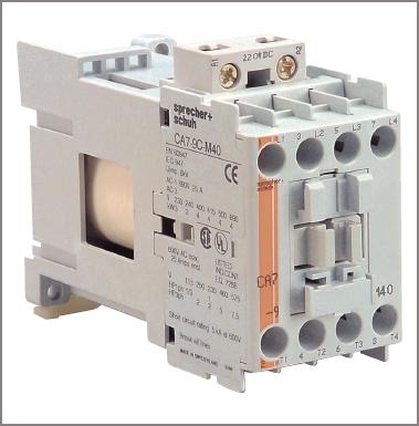
Figure 13 An electronic overload relay
The current setting can be adjusted for different electric motor run-up times by the use of DIL switches. Additional clip-on modules can be added to give further features such as remote-tripping, device-net, PTC thermistor relays and Ethernet connections.
Electric Motor Protection Devices Key Takeaways
The protection devices discussed—such as fuses, circuit breakers, over-current relays, thermal overloads, and temperature-dependent resistors—play a vital role in ensuring the safe and reliable operation of electric motor circuits. These components safeguard motors from common electrical faults like overloads, short circuits, under-voltage, and overheating, all of which can lead to significant equipment damage or operational downtime if left unaddressed. Their application is especially critical in industrial and commercial environments where motors are central to production and automation. By integrating these protection systems into motor control circuits, engineers can extend equipment lifespan, enhance system efficiency, and ensure the safety of personnel and infrastructure.