This article covers important aspects of voltage regulation in power supplies including the load resistor and voltage divider. It also touches on a voltage regulator circuit— a method to provide a constant voltage output at the power supply under varying load conditions.
The output voltage of a power supply will usually decrease when a load is applied. This decrease is not good and needs to be minimized. The size of this decrease is measured in comparison to the no-load voltage.
The voltage decrease under load compared to the power supply voltage with no load is called the percentage of voltage regulation.
It is one factor used to determine the quality of a power supply. Expressed mathematically:
\[Percentage\text{ }Voltage\text{ }Regulation=\frac{{{E}_{nl}}-{{E}_{fl}}}{{{E}_{fl}}}\times 100\]
Where Enl equals voltage with no load, and Efl equals voltage with full load.
Voltage Regulation Example 1
A power supply has a no load voltage of 30 volts. This voltage drops to 25 volts when a load is applied. What is its percentage of voltage regulation?
\[Percentage\text{ }Voltage\text{ }Regulation=\frac{{{E}_{nl}}-{{E}_{fl}}}{{{E}_{fl}}}\times 100\]
\[Percentage\text{ }Voltage\text{ }Regulation=\frac{30V-25V}{25V}\times 100=20%\]
Load Resistor
To complete the basic power supply circuit, a load resistor is connected across the supply, Figure 1. This resistor serves three important purposes.
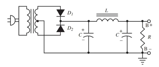
Figure 1. Complete power supply circuit with the load resistor.
First, the load resistor serves as a bleeder. A bleeder allows charged capacitors to drain. During operation of a power supply, peak voltages are stored in the capacitors of the filter sections. These capacitors remain charged after the equipment is turned off. These capacitors can be dangerous if accidentally touched by a technician.
The load resistor allows these capacitors to discharge when not in use. The wise technician will always take an added precaution and short capacitors to the ground with an insulated screwdriver.
Second, the load resistor improves regulation. The load resistor acts as a preload on the power supply. It causes a voltage drop. When equipment is attached to the power supply, the added drop is fairly small and the regulation is improved.
Voltage Regulation Example 2
Assume the terminal voltage of a power supply is 30 volts with no load resistor. No equipment is connected to it. When equipment is connected and turned on, the voltage drops to 25 volts. Regulation is 20 percent. (See the previous example under voltage regulation.)
If the resistor across the power supply produces an initial drop to 26 volts, then the output voltage is considered 26 volts. If the equipment now connected to the power supply causes the voltage to drop to 25 volts, then the power supply voltage regulation is:
\[Percentage\text{ }Voltage\text{ }Regulation=\frac{{{E}_{nl}}-{{E}_{fl}}}{{{E}_{fl}}}\times 100\]
\[Percentage\text{ }Voltage\text{ }Regulation=\frac{26V-25V}{25V}\times 100=4%\]
The usable voltage of the supply has only varied four percent.
A further advantage of preloading the power supply is an increase in the choke filtering action. The resistor allows current to flow in the supply at all times. A choke has better filtering action under this current condition than when current varies between a low value and zero.
Third, the load resistor acts as a voltage divider. The load resistor provides a way of obtaining several voltages from the power supply.
Replacing the single-load resistor with separate resistors in series provides several fixed dc voltages, Figure 2. A sliding tap resistor can also be used to provide voltage adjustments.
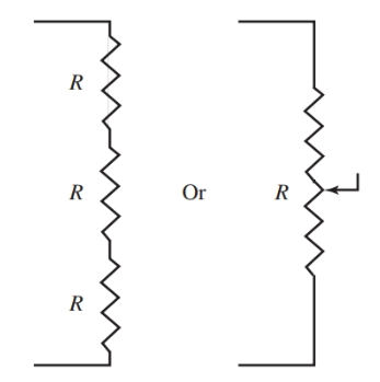
Figure 2. Voltage divider across power supply output.
This circuit is called a voltage divider. It takes advantage of Ohm’s law (the voltage drop across a resistor equals current times resistance, or E = I × R). In Figure 2, the and, therefore, changes the voltage at that tap.
Voltage Divider Example
In part A of Figure 3, the voltage divider consists of three five-kilohms (kΩ) resistors. The supply of 30 volts divides to 10 volts, 20 volts, and 30 volts at terminals C, B, and A respectively. In part B, a load of five kilohms is connected to terminal C as shown. It is parallel with R3 and resistance becomes:
\[{{R}_{T}}=\frac{{{R}_{3}}\times {{R}_{L}}}{{{R}_{3}}+{{R}_{L}}}=\frac{5000\Omega \times 5000\Omega }{5000\Omega +5000\Omega }=2500\]
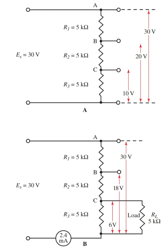
Figure 3. Diagrams show a change in resistance in a voltage divider when a load is attached.
The total resistance across the power supply with RL connected is 5000 Ω + 5000 Ω + 2500 Ω = 12,500 Ω. Now the current through the divider can be calculated.
\[I=\frac{{{E}_{source}}}{R}=\frac{30V}{12,500\Omega }=0.0024A=2.4mA\]
Using the total current, we can calculate the individual voltage drops. The voltage at point C is:
${{E}_{C}}=I\times R=0.0024A\times 2500\Omega =6V$
The voltage at point B is 18 volts. If another load were connected to point B, a further change of voltage division would result.
Voltage Regulator Circuit Diagram
Some method for providing a constant voltage output at the power supply under varying load conditions is needed. This method would take into consideration the fact that a voltage drop across a resistor is equal to the product of current and resistance. This method comes in the form of a circuit called a voltage regulator. It is shown in Figures 4 and 5. The total input of the power supply filter is applied to terminals A and B. Regulated output is across points C and B.
The voltage regulator used in Figure 4 is often called a three terminal fixed voltage regulator. Common output regulated voltages can be 5, 6, 8, 12, 15, 18, 24 volts, etc. (Various current ratings are also available from manufacturers.)
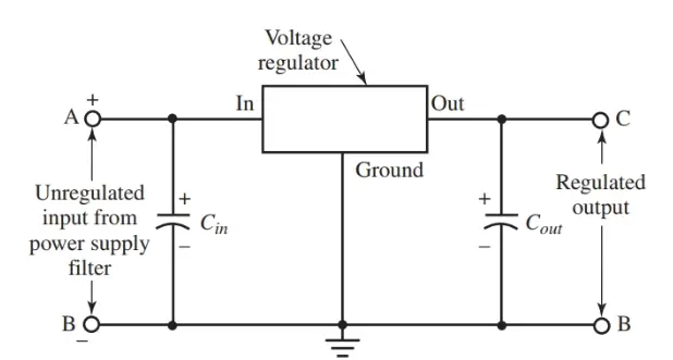
Figure 4. Basic voltage regulator circuit diagram


Figure 5. Schematic and connection diagrams for voltage regulators. (National Semiconductor Corp.)
Voltage Regulators come in a number of common transistor package designs (TO-3, TO-39, TO-202, TO-220, etc.). These solid-state regulators are basically blowout proof. They require that a heat sink is used to remove excess heat from the device.
The internal circuits used for these voltage regulators are quite complex. They have a number of transistors, diodes, Zener diodes, and resistors built into one small package. Figure 5 shows two voltage regulator schematics and their package designs.
An example of a use for a voltage regulator can be seen in an automobile. An automobile’s voltage regulator controls the voltage level from the alternator.
Voltage Regulation in Power Supply Key Takeaways
Understanding voltage regulation and the roles of load resistors, voltage dividers, and voltage regulator circuits is essential for ensuring the consistent and safe operation of electrical and electronic systems. These components and concepts help maintain a stable output voltage despite varying load conditions—an important requirement in sensitive equipment like computers, communication devices, and automotive electronics. Load resistors not only enhance safety by discharging capacitors but also improve voltage stability and filtering. Voltage dividers allow designers to derive multiple voltage levels from a single source, making circuits more efficient and versatile. Most importantly, voltage regulators provide a reliable, constant voltage output necessary for preventing damage and ensuring the proper functioning of modern electronic devices.