| 1. | With regards to measuring current and voltage in an AC circuit, modern AC instruments are calibrated to read:
|
| 2. | The current waveform for a purely resistive circuit:
|
| 3. | Look at the following figure:  Figure shows the voltage, current and power waveshapes for a purely resistive circuit supplied with a sinusoidal AC voltage. The waveshapes show that for a purely resistive circuit, the power curve:
|
| 4. | The power consumed by a purely resistive AC circuit can be determined using the following formula: P = Vrms x Irms In the formula, the symbol ‘P’ stands for the:
|
| 5. | Figure shows a non-inductive resistor: 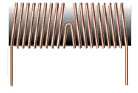 The non-inductive effect is produced by winding:
|
| 6. | A pure resistance of 15 ohms has been connected across an AC power supply that generates a pure sinewave of 84.84 volts peak voltage. The average power consumed by this resistor will be approximately:
|
| 7. | In an inductive AC circuit, the current is continually changing in value and direction, generating an induced EMF that will continually:
|
| 8. | Figure 3 shows the waveforms of the voltage and current in a purely inductive AC circuit: 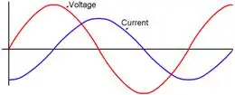 Using the voltage phasor as the reference, the current phasor:
|
| 9. | On AC, the change in current flow gives rise to an induced EMF that opposes the current flow. The effect of this current opposition is called:
|
| 10. | The inductive reactance in an AC circuit can be calculated from the formula: XL = 2 π f L In the formula, the symbol ‘L’ stands for the:
|
| 11. | A coil has an inductance of 0.04 H. The inductive reactance of the coil at a frequency of 50 Hz will be:
|
| 12. | A 230 V 50 Hz supply has been applied to a coil with an inductance of 0.15 H. The current in the circuit will be approximately:
|
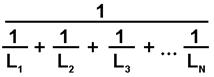
| 13. | When inductors are connected in series in an AC circuit, the total inductance can be found using the formula, Ltotal =
|
| 14. | Two inductors, one with an inductive reactance of 15 Ω, and the second with an inductive reactance of 10 Ω have been connected in series across a 230 V 50 Hz supply. The total inductive reactance will be:
|
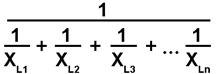
| 15. | Two inductors, one with an inductive reactance of 12 Ω, and the second with an inductive reactance of 8 Ω have been connected in parallel across a 230 V 50 Hz supply. The total inductive reactance will be:
|
| 16. | Figure shows the voltage, current and power waveshapes for purely inductive circuit:  The power waveshape shows that power is:
|
| 17. | A pure inductor with an inductive reactance of 150 W has been connected to a 230 V AC circuit. The average power consumed by this inductor is:
|
| 18. | In a purely capacitive circuit the current:
|
| 19. | Figure shows the waveshapes of voltage, current and power for a purely capacitive circuit: 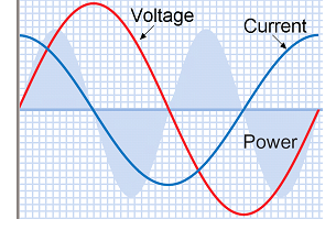 In this circuit, the current:
|
| 20. | The capacitive reactance of a capacitor can be determined using the formula: In the formula the symbol ‘f’ stands for the:
|
| 21. | A 16 uF capacitor has been connected to a 230 V 50 Hz supply. The capacitive reactance of this capacitor in this circuit will be approximately:
|
| 22. | When two capacitors are connected in series, the total capacitance:
|
| 23. | When two capacitors are connected in parallel, the total capacitance:
|
| 24. | An 22 uF capacitor has been connected in series with a 47 uF capacitor. The total capacitance of the combination is approximately:
|
| 25. | An 16 uF capacitor has been connected in parallel with a 22 uF capacitor. The total capacitance of the combination is approximately:
|
| 26. | Two 10 uF capacitors have been connected in parallel across a 230 V AC supply. The current drawn from the supply will be approximately:
|
| 27. | The average power consumed by a purely capacitive circuit:
|
| 28. | Figure shows a resistor and an inductor connected in series across an AC supply: 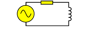 In this circuit, the current will:
|
| 29. | Figure shows the phasor diagram for an AC circuit with resistor and capacitor in series: 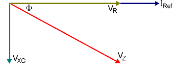 The diagram shows that in this type of circuit, the current phasor:
|
| 30. | In an AC circuit containing resistance, inductance and capacitance in series, the voltage drop across the inductor will:
|
| 31. | The following phasor diagram is for a resistor, inductor and capacitor connected in series across an AC supply: 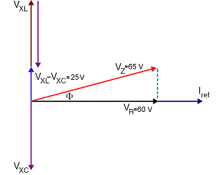 The value of the phase angle F is:
|
| 32. | The following formula can be used to determine the impedance of an AC circuit with resistance, inductance and capacitance in series: Z = √(R2 + (XL – XC)2) In the formula, the term XL stands for the value of the:
|
| 33. | A resistance of 50 Ω has been connected in series with an inductive reactance of 160 Ω and a capacitive reactance of 40 Ω. The impedance of the circuit will be:
|
| 34. | In a parallel AC circuit, the voltage is:
|
| 35. | Figure shows a resistor and inductor connected in parallel across an AC supply:  In this circuit, the current through the inductor will:
|
| 36. | Figure shows a resistor connected in parallel, with an inductor and resistor in series, across an AC supply. 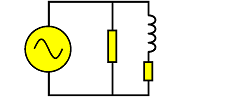 In this circuit, the current through the inductor will:
|
| 37. | Figure 10 shows the phasor diagram for a resistor and capacitor connected in parallel across an AC supply: 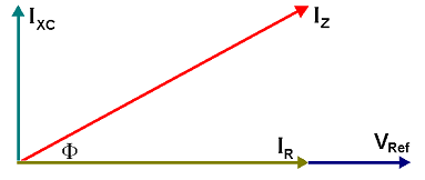 In this circuit, the current through the capacitor:
|
| 38. | When drawing the phasor diagram for R, L and C in parallel across an AC supply, the reference phasor is normally the:
|
| 39. | In an, AC circuit with R, L and C in parallel, the total supply current is:
|
| 40. | A resistance of 57.5 Ω has been connected to a 230 V 50 Hz supply, in parallel with an inductive reactance of 57.5 Ω and a capacitive reactance of 230 Ω. The total supply current will be:
|
| 41. | An AC circuit with R, L and C in parallel, has the following branch currents. Resistive branch – 12 A Inductive branch – 11 A Capacitive branch – 6 A The phase angle between the supply voltage and the supply current will be approximately:
|
| 42. | When resistance and inductance are combined in one circuit, there will be a value of power consumed that is dependent on the:
|
| 43. | The true power consumed by a single-phase AC circuit can be determined using the formula:
|
| 44. | In an AC the product of the measured line voltage and line current is called the:
|
| 45. | The reactive power in an AC circuit is sometimes called:
|
| 46. | Figure shows the power triangle for an AC circuit: 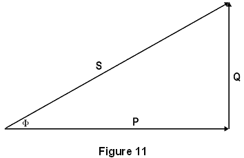 In the diagram, the side marked ‘S’ represents the:
|
| 47. | In an AC circuit, the power factor is the factor by which the apparent power is multiplied to obtain the:
|
| 48. | For all electrical power work with sinusoidal waveforms, the power factor is equal to the:
|
| 49. | Generally, the lower the value of the power factor in an AC circuit, the:
|
| 50. | One of the major causes of a low power factor is:
|
| 51. | The power factor of an AC circuit can be found using the formula, Power factor = :
|
| 52. | A single phase motor draws 2.175 A from a 230 V supply. A wattmeter in the circuit shows 400 W. The power factor of this circuit is approximately:
|
| 53. | An inductor draws 11.5 A on 230 V DC and 5.75 A when connected to 230 V AC. The angle of lag between the voltage and current when on AC will be:
|
| 54. | Look at the following diagram: 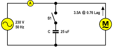 When the switch S1 is closed in figure, the reading on the ammeter will:
|
| 55. | Look at the following diagram: 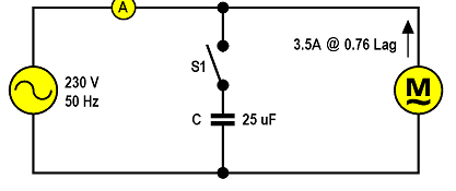 When the switch S1 is closed in figure, the power factor of the circuit will:
|
| 56. | Figure shows the phasor diagram of an electric motor connected to 230 V AC supply: 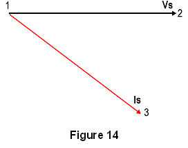 If a capacitor is connected in parallel with the motor, the phasor to represent the capacitor current would be drawn:
|
| 57. | A single-phase 230 V 50 Hz induction motor draws 7.5 A at 0.6 power factor. If a 47 μF capacitor is connected across the line, then the combined line current will be approximately:
|
| 58. | The purpose of using capacitors to improve the power factor is to provide a:
|
| 59. | When using a power triangle to solve AC circuits the reactive power can be found using the formula: Q = V I √1 – PF2) In the formula the symbol PF stands for the:
|
| 60. | When an electrical circuit has its power factor corrected to unity, the current is:
|
| 61. | In an AC circuit, when the capacitive reactance and inductive reactance are exactly equal, the circuit is said to be:
|
| 62. | The major characteristics of the series resonant circuit are a power factor of unity and a:
|
| 63. | When an inductor and capacitor are connected in parallel and their respective reactances are equal, the reactive currents are:
|
| 64. | When the supply frequency to a parallel resonant circuit is varied, the resistance in the circuit is unchanged but the impedance will be:
|
| 65. | In an AC circuit at resonance, energy is being transferred back and forth from the:
|
| 66. | A 10 Ω resistor, 0.25 H inductor and a 40.52 μF capacitor have been connected in series across a variable frequency AC supply. The resonant frequency of the circuit will be:
|