| 1. | Resistance can be described as the:
|
| 2. | The resistance of a material is most commonly determined by four factors-length, cross-sectional area, type of material and:
|
| 3. | The resistance of a conductor is proportional to its:
|
| 4. | The resistance of a conductor is inversely proportional to its:
|
| 5. | Look at the following table: 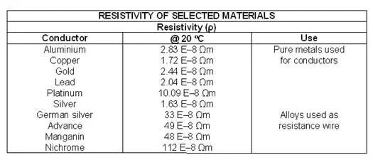 The above table gives the resistivity of some common materials used in the electrical industry. The best conductor shown on the table is:
|
| 6. | Resistivity of a material is defined as the:
|
| 7. | The following formula can be used to determine the resistance of a length of conductor. In the formula the symbol ρ stands for the:
|
| 8. | A copper cable has a length of 450 m and a cross-sectional area of 4.0 mm2. If the resistivity of the copper is 1.72E-8 Ωm, then the resistance of this cable will be:
|
| 9. | A 10 Ω resistor is to be made from manganin wire with cross-sectional area of 0.2 mm2. If manganin has a resistivity of 48 E–8 Ωm, then the required length of this size manganin wire will be:
|
| 10. | The temperature coefficient of resistance of a material is defined as the change in:
|
| 11. | For some materials, an increase in temperature causes an increase in resistance; these materials are said to have a:
|
| 12. | Look at the following graph:  The above graph shows the effect of an increase in temperature on a copper conductor. The graph shows that the increase of resistance plotted against temperature is:
|
| 13. | The inferred zero formula for determining the resistance of a copper conductor is shown: In the formula, the term t2stands for the:
|
| 14. | The resistance of a coil of copper wire is 30 Ω at 15ºC. Its resistance at 75ºC will be:
|
| 15. | An electric motor has a winding resistance of 15 Ω at 20ºC. After running up to temperature at full load the resistance is measured as 19 Ω. The temperature of the windings will now be:
|
| 16. | The temperature coefficient of resistance is defined as the change in:
|
| 17. | The above formula can be used to determine the resistance of a conductor using the temperature coefficient of resistance method. In the formula the term R1 stands for the:
|
| 18. | If copper conductor has a resistance of 15 Ω at 0ºC, then using the temperature coefficient of resistance method (Note: Consider the temperature coefficient of resistance of copper to be 0.004 27 Ω/Ω/ºC at 0°C.), its resistance at 20ºC will be:
|
| 19. | The supply to a 15A air-conditioning unit consists of copper conductors with a cross-sectional area of 2.5 mm2 and a total resistance of 0.38 Ω. When the air-conditioner is operating, the power lost in the conductors will be:
|
| 20. | Many materials produce an effect known as ‘superconductivity’ when they are cooled below a certain temperature. At the critical temperature:
|
| 21. | When current flows through a conductor, the conductor will heat up. If the conductor temperature exceeds the insulation rating of the cable then the:
|
| 22. | A resistance of 120 Ω is required to carry 200 mA of current. The value of power dissipation required by this resistor is:
|
| 23. | Smaller value resistors, from 5 watts to several hundred watts, are commonly:
|
| 24. | The E12 range of preferred values of resistors is based on a tolerance of:
|
| 25. | Look at the following diagram: 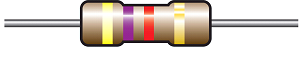 The size of the above resistor is:
|
| 26. | Look at the following diagram:  The above diagram shows the characteristic for a typical PTC thermistor. For an increase in temperature, the resistance of the thermistor will:
|
| 27. | Look at the following diagram: 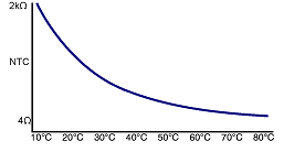 The above diagram shows the characteristic for a typical NTC thermistor. For an increase in temperature between 50°C and 60°C, the resistance of the thermistor:
|
| 28. | The voltage dependent resistor normally only conducts when the:
|
| 29. | Light-dependent resistors are used to detect light levels such as in PE (photo-electric) cells on power poles to turn street lights on and off, or to control other night lighting. When light falls on the resistor:
|
| 30. | Liquid resistors are often used in motor starters. One advantage of liquid resistance is that the resistance value:
|