| 1. | The only AC waveform that produces a current flow with the same waveform as the voltage is the:
|
| 2. | Look at the following diagram: 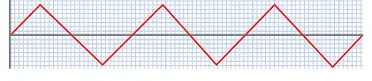 The waveshape shown in the diagram is:
|
| 3. | When the positive period of an AC waveshape is not equal to the negative period, the waveform is known as:
|
| 4. | A rotating machine producing a voltage with an alternating waveform at its terminals is called:
|
| 5. | Look at the following diagram:  If the loop is rotated continuously, the output will be:
|
| 6. | The following formula can be used to determine the value of the voltage induced in a rotating loop: In the formula the term B stands for the:
|
| 7. | Look at the following diagram:  The basic construction of an alternator has been shown to be a loop rotating in a magnetic field, as illustrated. This result can also be achieved by:
|
| 8. | A conductor 0.25 m long is rotating on the periphery of an armature at 25 ms–1. If the flux density is 0.3 T, then the voltage induced in the conductor when it is cutting the field at an angle of 60º will be approximately:
|
| 9. | The iron core onto which the coils of an alternator are wound improves the voltage output by increasing the flux density, but causes two undesirable effects, these are:
|
| 10. | In an alternator, hysteresis loss results in energy loss in the form of:
|
| 11. | The eddy-current losses in alternators may be greatly reduced by using cores which are made of:
|
| 12. | The hysteresis losses in the core of an alternator can be kept within reasonable limits by using:
|
| 13. | Some of the design techniques used in alternators such as, distributed windings, variation of air gaps and the setting of conductors at an angle, are used to:
|
| 14. | In Australia, the standard frequency of supply is:
|
| 15. | Look at the following drawing: 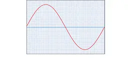 The drawing shows a sinewave of voltage. If the voltage has a frequency of 50 Hz, then the periodic time of the waveshape will be:
|
| 16. | The frequency of the output voltage of an alternator can be determined using the following formula: f = n P/120 In the formula the term P stands for the:
|
| 17. | In order to generate a voltage at a frequency of 50 Hz, a 6 pole alternator must each be driven at a speed of:
|
| 18. | Look at the following diagram: 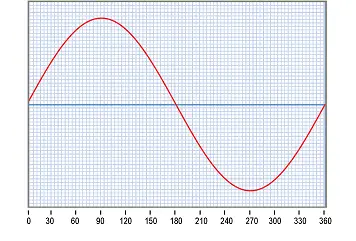 With reference to the sinewave of voltage shown, if the maximum value of the voltage is 340 volts, then the value of the instantaneous voltage at 30 ° will be:
|
| 19. | A sinewave of current has a maximum value of 15 amperes. Using the formula I = Imax sin θ the instantaneous current at 60° will be approximately:
|
| 20. | A sinewave of current has a maximum value of 12 amperes. The average value of current will be approximately:
|
| 21. | A sine wave of voltage has a maximum value of 155.6 V. The RMS value of the voltage will be approximately:
|
| 22. | For any waveform, the crest factor is defined as the ratio of the:
|
| 23. | For any waveform, the form factor is defined as the ratio of the:
|
| 24. | For a sinewave, the form factor is:
|
| 25. | Look at the following diagram: 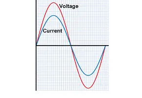 With reference to the diagram, the current:
|
| 26. | When drawing a phasor diagram for a series AC circuit, the:
|
| 27. | Look at the following diagram:  With reference to the diagram, the current is shown:
|
| 28. | Look at the following diagram: 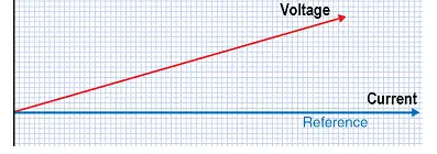 In the phasor diagram shown, the:
|
| 29. | Two voltages A and B have been connected in series. Voltage A is 100 V and leads the current by 30º, while voltage B is 80 V and lags the current by 25º. Using the trigonometric method, the resultant voltage will be approximately:
|
| 30. | A perfect square wave would consist of:
|