| 1. | A three-phase generating system has an efficiency of around:
|
| 2. | The windings of a three-phase alternator are separated by:
|
| 3. | Figure shows the stator winding arrangement of a 4 pole, three phase alternator: 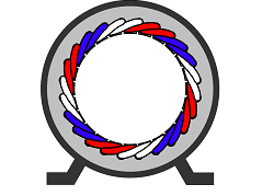 The alternator has a 24-slot stator and is wound with 24 coils in sets of:
|
| 4. | One of advantages of a three-phase system over a single phase system is that the power is more constant so that the torque of a rotating machine is more constant. The more constant torque results in:
|
| 5. | Figure shows the waveform for a three-phase AC supply:  The displacement between the voltage is:
|
| 6. | In a three-phase system, where the three voltage sources are, connected to feed a three-phase load, the phase sequence is important for rotating machinery, because the:
|
| 7. | One method of forming a three-phase system is to connect the three similar ends of the windings together at one point. This type of connection is called a:
|
| 8. | Look at the following diagram: 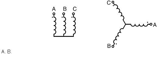 The three-phase winding shown in figure have been connected in the:
|
| 9. | Look at the following diagram: 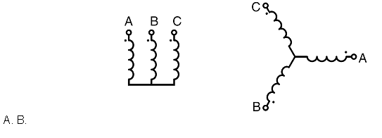 The three-phase winding shown in figure has:
|
| 10. | In a three-phase star-connected system the line current equals:
|
| 11. | In a three-phase star-connected system the line voltage equals:
|
| 12. | Figure shows one method of determining the line voltage of a three-phase star connected system: 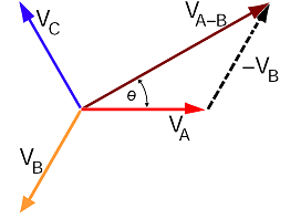 In the diagram, the line voltage phasor VA-B is equal to:
|
| 13. | In a star connected three-phase system, the line voltages:
|
| 14. | Figure shows the phasor diagram method of determining the line voltage of a three-phase star connected system: 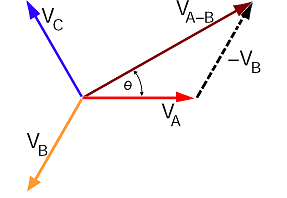 In the diagram, the line voltage phasor VA-B:
|
| 15. | Figure shows the phasor diagram of a three-phase star connected system in which phase “C” phase has mistakenly been connected with the connections reversed: 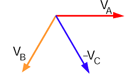 The waveforms of the three phase voltages then have a displacement of 120º E between A and B, and:
|
| 16. | One method of forming a three-phase system is to connect the dissimilar similar ends of the windings together. This type of connection is called a:
|
| 17. | Look at the following diagram: 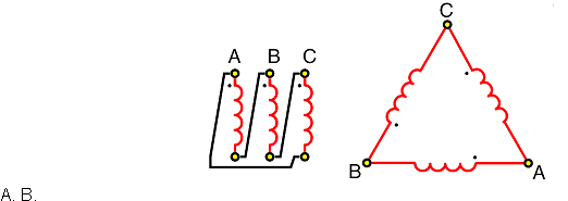 The three-phase winding shown in figure have been connected in the:
|
| 18. | In a three-phase delta-connected system the line current equals:
|
| 19. | In a three-phase delta-connected system the line voltage equals:
|
| 20. | Figure shows one a Delta connected 400 V three-phase system in which one phase has been mistakenly connected with reversed connections: 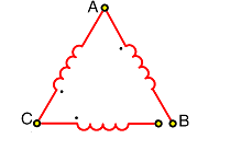 In the diagram, the voltage between the open connections will be:
|
| 21. | Figure shows a connection diagram for a three-phase delta connected load:  The current in line 2, equals the:
|
| 22. | Figure shows a phasor diagram for determining the line current in a three-phase delta connected load: 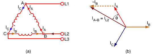 In the diagram, the line current phasor IL2:
|
| 23. | Electrical power can be transmitted using low voltage and high currents. Higher currents result in:
|
| 24. | In economic terms, the higher the voltage used for power transmission systems, the:
|
| 25. | Look at the following diagram: 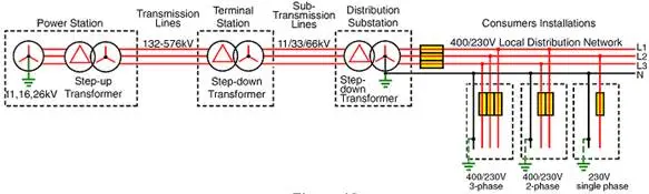 Transmission system voltages are far higher than the voltages required by the average consumer, therefore the voltage is:
|
| 26. | 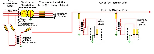 The distribution system shown in figure is a:
|
| 27. | Figure shows a 4-wire distribution system with the star point of the phase windings connected to earth: 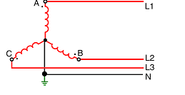 One advantage of this system is that:
|
| 28. | For a balanced load, the current in a neutral conductor of a three-phase, four-wire system is equal to:
|
| 29. | For any type of load, the current in a neutral conductor of any three-phase, four-wire system is equal to:
|
| 30. | The currents in the lines of a three-phase four-wire system are: A phase—8 amperes at unity power factor B phase—10 amperes at 0.866 leading power factor C phase—10 amperes at 0.866 lagging power factor. In this case the current flowing in the neutral conductor will be approximately:
|
| 31. | Figure shows the readings obtained when checking the voltages of a faulty 230/400 V three-phase four-wire system: 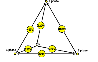 The most likely cause of the fault will be a:
|
| 32. | The power consumed by a three-phase load can be determined using the formula:
|
| 33. | A three-phase 400 V motor draws 10 A at 0.8 lagging power factor. The power is consumed by this motor will be approximately:
|
| 34. | Figure shows the one wattmeter method of measuring three-phase power on a three-phase four-wire system: 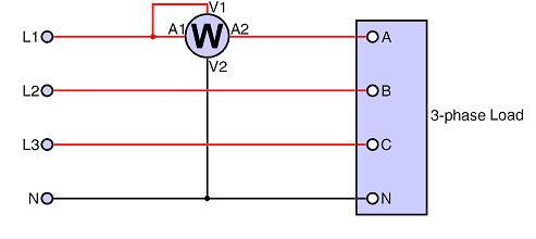 One advantage of this method is that:
|
| 35. | Figure shows the two-wattmeter method of measuring power in a three-phase three-wire system:  One advantage of using this method is that:
|
| 36. | The power consumed by a three-phase motor has been measured using the two-wattmeter method. At full load, the two wattmeters gave readings of 6 kW and 3 kW. At this load, the power factor of the motor will be:
|
| 37. | Figure shows the three-wattmeter method of measuring three-phase power in a three-phase four-wire system: 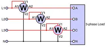 To find the total power, the following calculation must be made using the readings: PTOTAL =
|
| 38. | Figure shows the three-wattmeter method of measuring three-phase power in a three-phase four-wire system. 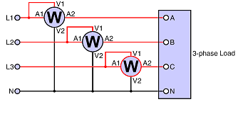 This method is suitable for:
|
| 39. | One advantage of using three-phase digital wattmeters is as well as the power, they can show the value of such things as:
|
| 40. | In power stations operating under normal conditions, the values of voltage and current are generally too high and unwieldy to be used directly with portable instruments. To avoid these high-energy circuits when measuring voltage, current and power, in these cases:
|