| 1. | A capacitor consists of two conducting surfaces called plates, separated by an insulating material called the:
|
| 2. | Capacitance is the measure of the ability of a capacitor to:
|
| 3. | A farad is the capacity of a capacitor that stores a charge of one coulomb at a potential difference of:
|
| 4. | A coulomb is the charge that passes a point in one second when a:
|
| 5. | The charge on a capacitor can be determined using the formula:
|
| 6. | A 15 uF capacitor has been charged to a potential difference of 240 V. The charge on the capacitor will be:
|
| 7. | The capacitance of a capacitor varies according to three physical parameters. These are, the effective area of the plates, the distance between the plates and the:
|
| 8. | For a capacitor consisting of two parallel plates, the capacitance can be found from the following equation: In the formula symbol ‘A’ stands for:
|
| 9. | The dielectric constant signifies the degree to which capacitance can be increased by replacing the:
|
| 10. | For a capacitor, the voltage per unit thickness necessary to cause breakdown is called the:
|
| 11. | When capacitors are connected in series the total capacitance will be:
|
| 12. | Look at the following diagram: 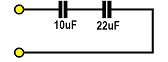 A 10 uF and a 22 uF capacitor have been connected in series as shown in the above diagram. The total resulting capacitance will be approximately:
|
| 13. | Look at the following diagram:  Two capacitors have been connected in series across a 24 V DC supply as shown. The voltage across the 33 uF capacitor will be:
|
| 14. | Placing two or more capacitors in parallel has the same effect as:
|
| 15. | Look at the following diagram:  Two capacitors have been connected in parallel as shown. The total capacitance will be:
|
| 16. | When a capacitor is connected to DC supply a charging current will flow. This current:
|
| 17. | The time constant is the time taken for a capacitor to charge up to:
|
| 18. | Look at the following diagram: 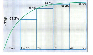 With reference to the time constant curve shown above, the percentage of the supply voltage on a capacitor three time constants after charging has commenced will be:
|
| 19. | Look at the following diagram: 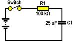 The time constant of the above circuit is:
|
| 20. | Look at the following diagram: 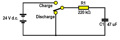 With reference to the above circuit, if the capacitor has been charged to 24 V, then the time taken to discharge to 15.16 V will be:
|
| 21. | Look at the following diagram: 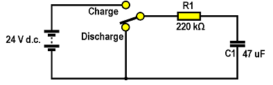 With reference to the above circuit, if the capacitor is fully discharged and the switch connected to the charge position, the capacitor voltage will reach 20.74 V in:
|
| 22. | The energy stored in the capacitor can be found using the formula:
|
| 23. | A 47 uF capacitor has been charged from a 200 V DC supply. The energy stored in the capacitor will be:
|
| 24. | Care must be taken when working with large value capacitors as they can:
|
| 25. | Look at the following diagram: 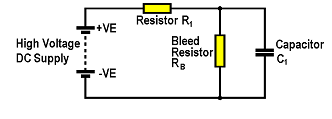 With reference to the above circuit, a high-value bleed-resistor has been permanently connected across capacitor C1 to:
|
| 26. | If an oil-filled capacitor has less than its rated capacitance then the most likely cause would be that:
|
| 27. | To test a large capacitor, an ohm-meter is placed across the terminals of a known discharged capacitor. If there is capacity in the capacitor the resistance will be:
|
| 28. | Look at the following diagram:  The capacitors shown are:
|