| 1. | In electric circuits, ‘inductance’ is the property of a circuit which:
|
| 2. | Inductors have the effect of storing current as an electromagnetic field whenever the current increases and:
|
| 3. | Look at the diagram: The following diagram shows the symbol for a:
|
| 4. | An EMF can be induced in a conductor if there is a relative movement between a conductor and:
|
| 5. | Faraday’s Law of electromagnetic induction states that the value of the EMF induced in a circuit depends on the number of conductors in the circuit and the rate of change of the:
|
| 6. | The following formula can be used to determine the voltage induced in a conductor by a moving magnetic field: In the formula, the ø stands for the:
|
| 7. | A coil of 400 turns is cut by a magnetic field of 0.15 Wb in 4 seconds. The voltage induced in the coil will be:
|
| 8. | The EMF generated in a conductor can be determined using the following formula: In the formula the θ symbol stands for the:
|
| 9. | A 15 cm conductor is rotated within a magnetic field of a constant density of 0.8 Tesla. If the velocity relative to the field is 12 m per second, then the voltage generated at a cutting angle of 45º will be:
|
| 10. | The inductive effect of Lenz’s law is such that the induced current will appear in such a direction that it:
|
| 11. | Magnetic inductance occurs when a magnet:
|
| 12. | In an electric circuit, inductance occurs when a current in one circuit causes:
|
| 13. | The value of inductance in an inductor is a function of the size and number of turns in the coil, the magnetic effects of the core and the:
|
| 14. | Look at the following photo: 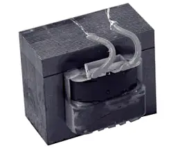 The photo shows:
|
| 15. | The henry is the inductance of a closed circuit in which an EMF of 1 volt is produced when the electric current flowing in the circuit varies uniformly at the rate of:
|
| 16. | The EMF generated in an inductor can be determined using the following formula: In the formula the L symbol stands for the:
|
| 17. | If the current through an inductor of 1.2 H is reduced uniformly from 6 A to 1 A in 0.4s, then the value of the induced EMF will be:
|
| 18. | The current in a 150 turn coil changes from 4 amps to zero amps causing a flux change of 200 mWb. The inductance of the coil is:
|
| 19. | The following formula can be used to determine the inductance of a coil from physical quantities. 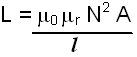 In the formula the term μo stands for the:
|
| 20. | An air cored coil with 50 turns of wire has been wound over a length of 100 mm on a plastic pipe with an outside diameter of 25 mm. The inductance of coil will be:
|
| 21. | The term ‘self-inductance’ is used when a conductor has a voltage induced in it by:
|
| 22. | When voltage is applied, to an inductor, a magnetic field builds up and in doing so, produces a generated voltage that:
|
| 23. | The inclusion of an iron core within a coil:
|
| 24. | With an inductor, the value of any induced voltage depends on the:
|
| 25. | The following diagram illustrates the relative directions and values of induced voltage during ‘circuit make’ and ‘circuit break:  The very high self-induced voltage occurring at ‘switch off’ is due to the:
|
| 26. | When opening highly inductive circuits, it is necessary to use a bypass circuit through which the high self induced voltage may be discharged. This bypass circuit is called a:
|
| 27. | Any two coils sharing a part of a magnetic field will experience:
|
| 28. | When inductors are placed in series, the total value of the inductance is determined by:
|
| 29. | The voltage across the inductor rises almost instantaneously to a maximum when switched on:
|
| 30. | An inductor is therefore said to have a time constant τ = tau) which is found from the formula: In the formula the symbol ‘L’ stands for the:
|
| 31. | The following diagram shows a time constant curve applied to the rise of current in an inductive circuit: 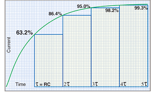 Three time-constants after switch on, the current will be:
|
| 32. | A 0.75 H choke has an internal resistance of 20 Ω. The time constant of the choke is:
|
| 33. | The energy that can be stored in the electromagnetic field around an inductor can be calculated from the following formula: In the formula the term ‘I’ stands for:
|
| 34. | A 6 H electromagnet with an internal resistance of 40 Ω has a current flowing through it of 5A. The energy stored in its fully charged magnetic field is:
|
| 35. | Care must be taken when working with large inductors as the energy in an inductor can be discharged very fast. This will result in the:
|
| 36. | Coils often have a magnetic core, such as laminated iron or ferrite added to:
|
| 37. | Toroidal cores of ceramic materials are popular in many areas of electronics and electrical engineering mainly because:
|
| 38. | Look at the following diagram: 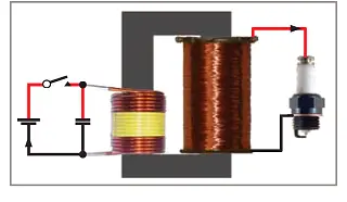 The diagram illustrates the principle of operation of a Kettering ignition system. The operation of this system is based on, which is based on:
|
| 39. | If the insulation on an inductor breaks down, it can present two common problems-shorted turns and:
|
| 40. | Broken conductors can occur in inductors, usually due to:
|
| 41. | The insulation resistance of inductors with more than one coil should be tested between coils and an insulation value greater than:
|
| 42. | The resistance of inductors can be measured to ensure that the coil has continuity. This test ensures that the:
|
| 43. | Before putting into service, relays using induction coils, should be given an insulation resistance test, a continuity test and:
|