A typical characteristic curve for a diode is shown in Figure 1. This curve shows the variation of the diode current versus the voltage across the diode.
On the right-hand side of the vertical axis (the current axis), a diode is forward biased because the voltage applied across it is positive. The left-hand side corresponds to reverse bias.
When a diode is forward biased, the current across it has an abrupt increase as the voltage increases. This represents a small resistance to the current flow.
On the contrary, for reverse bias, the diode exhibits a large resistance and the current is, thus, very small (negligible). When reverse biased, the diode can withstand the voltage across it up to a certain limit before breaking down. When the voltage surpasses the breakdown voltage, an ordinary diode gets damaged and there is a sudden increase in current.
When a diode is damaged, it becomes useless and cannot withstand any voltage. The point at which breakdown happens is called the breakdown point, and the high current after this point is called the avalanche current.
Breakdown voltage: Voltage at which a semiconductor device changes behavior or gets damaged.
Breakdown point: Point in the characteristic curve of a semiconductor device where the applied voltage is beyond the limit that the device can stand without a sudden change in behavior or without getting damaged.
Avalanche current: Relatively higher current in a semiconductor device after breakdown occurs.
In general, one can say that a diode characteristic curve consists of three lines. This is true except around the origin, which is different.
Remember that a voltage of 0.7 V is required for a silicon-based PN junction to conduct (0.3 V for germanium). This implies that the line corresponding to the forward bias region does not start from the origin, but from 0.7 V point on the horizontal axis.
Note that in Figure 1 the slopes of the curves are moderated for clarity. In reality, the slopes of these lines are more vertical or more horizontal than those shown.
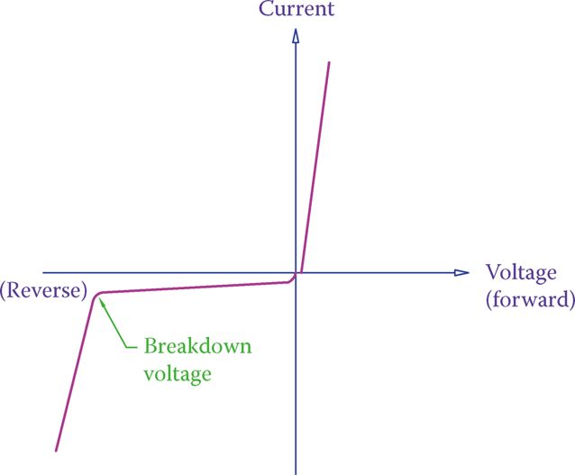
Figure 1 Diode characteristic curve.
Similar to any other device or electric component, a diode has ratings for maximum voltage and maximum current. For example, a small diode may have a rating of 1 A; thus, it should not be used in a circuit with more than 1 A current (unless it is used in parallel with some other diodes).
A higher rated diode may be suitable for a circuit with, say, 200 A current. Figure 2 shows a special diode for power electronics, with a high current capacity.
In addition to the above ratings, a diode has a rating for the reverse voltage. This is the maximum voltage that a diode can withstand in the reverse bias before exhibiting an avalanche current and getting damaged.
For any application, the peak inverse voltage (PIV), also called peak reverse voltage (PRV), the rating of a diode must be considered for the maximum voltage across the diode in the reverse bias condition.
Peak inverse voltage (PIV): It is the maximum reverse bias voltage that a diode can withstand without getting damaged (breaking down). This is important in the selection of diodes in the design of rectifiers. It is also called Peak Reverse Voltage (PRV).
Peak reverse voltage (PRV): The same as Peak Inverse Voltage (PIV).
When in a circuit, a diode needs a small voltage across it in order to conduct.
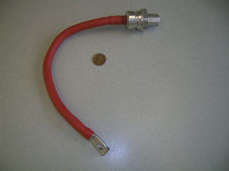
Figure 2 A special high current diode.
When using a diode in a circuit, its voltage and current ratings and also its peak reverse voltage rating must be brought into consideration.