The article provides an overview of the basic working principles of a radio transmitter and receiver, covering key components, signal processing methods, and types of wave propagation. It also highlights the role of microphones in converting audio signals, emphasizing their importance in the overall performance of a radio transmitter and receiver system.
For a basic understanding of radio and television operations, we will first look at a simple radio receiver. This radio receiver consists of very few parts, an antenna, a ground, a tank circuit, a diode, a filter, and a speaker or a set of headphones.
Radio Receiver Working Principle
In Figure 1, there are three radio stations each broadcasting at a different wavelength. Each station is broadcasting a radio signal consisting of a carrier wave and an audio signal. Station 1 is broadcasting at AM 920, station 2 at AM 1460, and station 3 at AM 1040.
Antenna
The radio waves of all three stations come in contact with the radio receiver antenna. The antenna converts the radio signals to alternating current, which is conducted up and down the antenna to the ground. The antenna circuit is coupled to the tank circuit by mutual induction.
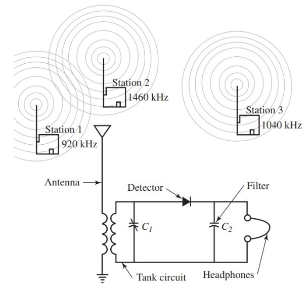
Figure 1. A simple crystal radio can receive AM radio signals and convert them to sound.
Tank Circuit
The tank circuit consists of an inductor and a variable capacitor connected in parallel. As we know that an inductor and capacitor connected in parallel will have a resonant frequency.
By using a variable capacitor, you are able to vary the tank circuit resonant frequency until it matches the frequency of the desired station.
For example, if we wish to tune in station 1, the capacitor is varied until the resonant frequency of the tank circuit is equal to 920 kHz. Receiving a frequency of 920 kHz will cause the greatest voltage drop across the tank circuit.
The other frequencies (1040 station 3, and 1460 station 2) will not produce a large voltage drop across the tank circuit.
Detector
The detector rectifies the radio signal to a pulsing dc signal. The filter capacitor smoothers the high frequency of the audio portion of the radio signal.
The detector diode and filter capacitor are necessary to change the broadcast frequency and audio signal to a reproducible sound at the headphones.
The description above may sound simple, and that is because this is the simple operation of a radio receiver. The radio described is known as a crystal radio receiver.
When constructed properly in the lab, you can actually receive and hear a few stations. The performance of this radio, however, is extremely poor by today’s standards.
Today’s radios and televisions operate from the same principles just described, but they are a significant refinement of the crystal set.
Take special note of the fact that there is no battery or other conventional power supply for this radio. First, we will discuss the power source for this radio.
Radio Waves
A radio wave is an electromagnetic radiation produced from current alternating through an antenna.
A transmitting antenna is surrounded by electromagnetic radiation. In the study of electromagnetism, we learned that a conductor carrying an electric current is surrounded by a magnetic field. In a magnetic field created by an alternating current, the field expands, collapses, and changes polarity in step with the frequency.
An oscillator can produce high-frequency alternating currents that produce a radio wave when connected to an antenna. In general, the radio wave is an electrostatic radiation of energy produced by an oscillator circuit.
The electrostatic field is perpendicular to the electromagnetic field. Both travel away from the antenna. As a result, a radio wave is made up of electromagnetic and electrostatic fields. See Figure 2. The direction these waves radiate, in respect to the earth, is called polarization.
In Figure 3 the waves are radiated from a vertical antenna. Note that the electrostatic, or E waves, are in the same plane as the antenna, yet perpendicular to the direction of travel. The vertically polarized waves are perpendicular to the surface of the earth.
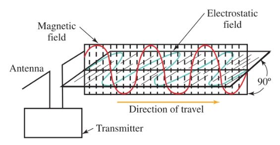
Figure 2. The relationship between electrostatic and electromagnetic waves. They are perpendicular to each other and both are perpendicular to the direction of travel.
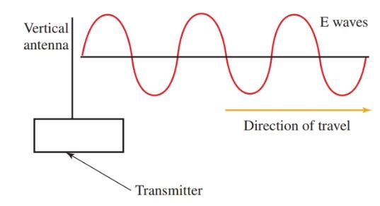
Figure 3. A vertical antenna radiates a vertically polarized wave.
In Figure 4, the wave is radiated from a horizontal antenna. It is still perpendicular to the direction of travel but is parallel to the surface of the earth.
Generally speaking, the antenna that receives these waves should be positioned in the same way as the transmitting antenna. At high frequencies, the polarization changes slightly as the wave moves.
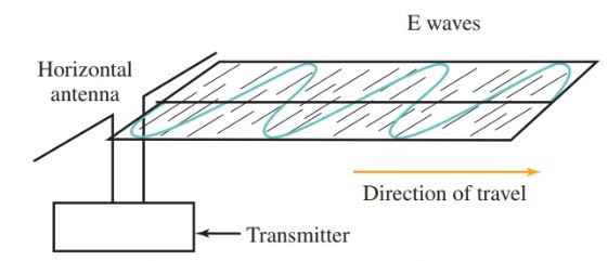
Figure 4. A horizontal antenna radiates a horizontally polarized wave.
Does all this mean the transmitting antenna radiates two waves? The answer is found in the fact that without one, there cannot be the other.
A moving electrostatic field produces a moving electromagnetic field, and likewise, a moving electromagnetic field produces a moving electrostatic field. These conditions exist whether an actual conductor is present or not.
The radiated waves from an antenna can be divided into two groups. These are ground waves and sky waves.
Ground waves
A ground wave follows the surface of the earth to the radio receiver. The ground wave has three parts:
- The surface wave.
- The direct wave, which follows a direct path from the transmitter to the receiver.
- The ground-reflected a wave, which strikes the ground and is then reflected the receiver.
The last two waves are combined and called a space wave. The waves that make up the space wave may or may not arrive at the receiver in proper order. They may join together or cancel each other, depending on distances traveled by each wave.
Broadcast stations depend on the surface wave for reliable communications. As the surface wave travels along the surface of the earth, it induces currents in the earth’s surface. These currents use up the energy contained in the wave. The wave becomes weaker as the distance it travels increases.
An interesting side note is that salt water conducts surface waves about 5000 times better than the land. Overseas communication is very reliable when transmitters are near the coastline. These stations use high power and operate at lower frequencies than the normal broadcast band.
Sky Waves
The second type of radiated wave is a sky wave. Sky waves use the ionized layer of the earth’s atmosphere for transmission. This layer is called the ionosphere. It is located from 40 to 300 miles above the earth’s surface. It is believed to consist of large numbers of positive and negative ions.
As the sky wave radiates, it strikes the ionosphere. Some of the waves can be absorbed into the ionosphere. But some will bounce off the layer and be sent back to the earth’s surface. See Figure 5.
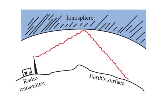
Figure 5. Sky waves bounce off the ionosphere and move back to the earth’s surface.
Radio Transmitter Working Principle
Any oscillator will produce radio frequency waves. When the oscillator is connected to an antenna system, it sends energy into the atmosphere. Amplification will increase the amplitude of the oscillator wave so that it will drive a final power amplifier.
Continuous Wave Transmitter
A block diagram of a simple continuous wave (CW) transmitter is shown in Figure 6. The first block is the conventional crystal oscillator and then the final power amplifier. A power supply is provided for the oscillator and the final power amplifier.
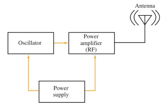
Figure 6. A block diagram representing various stages of a basic continuous wave radio transmitter.
Following the action in Figure 6, the oscillator creates an ac sine wave at the desired frequency. This signal is called the carrier wave. The carrier wave is then amplified by the radio frequency (RF) power amplifier to the desired output wattage.
A power supply is required to provide the voltages and current needed to operate the oscillator and the RF power amplifier. The output is then fed to an antenna. From there, the energy is sent into the air as electromagnetic waves.
Notice that a CW transmitter sends energy that has no audio or video message. The CW transmitter has only two states, on or off. How can this type of transmitter be useful? By adding a switch, the transmitter can be turned on and off following a code. For example, such a transmitter could be used to send Morse code messages, Figure 7. Figure 8 lists the character set for sending Morse code messages.
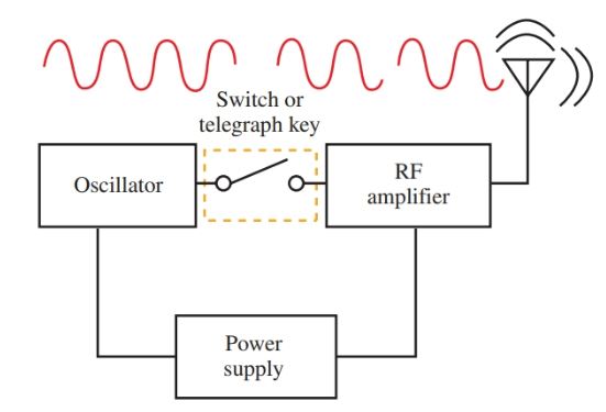
Figure 7. Continuous wave transmitter with a telegraph key. Note break in RF waveform indicating an open switch at that point.
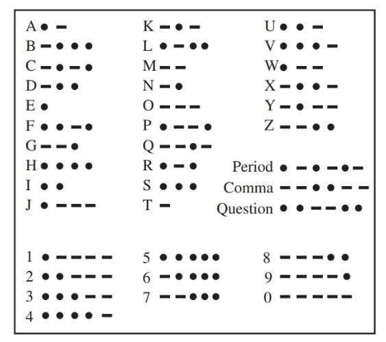
Figure 8. The character set for Morse code.
The basic switched, or keyed, CW transmitter can be improved by placing a buffer amplifier between the oscillator and the RF amplifier.
The buffer amplifier isolates the oscillator from the RF amplifier and keeps it from shifting off of the desired frequency. It also provides some amplification to the carrier wave.
Many CW transmitters use frequency multipliers to increase the frequency produced by the basic oscillator. These circuits multiply the carrier wave by two (doubler) or three (tripler). These circuits operate on the principle of harmonics in the fundamental carrier frequency created by the oscillator.
A fundamental frequency is a basic frequency produced by the oscillator. A harmonic frequency is a multiple of the fundamental frequency.
Microphones
How is a sound wave converted to an electrical wave? Your vocal cords send vibrations in the air. These waves move out to all persons within hearing range.
A microphone will convert these sound waves into electrical audio waves of the same frequency and relative amplitude. Microphones are sometimes called transducers. This is because they transform one form of energy (vibrating air, or mechanical) to electrical energy. Figure 9 shows a microphone built into a video camera.

Figure 9. This video camera is equipped with a stereo microphone. (Sony Electronics Corp.)
Carbon microphone
A diagram of a carbon microphone is shown in Figure 10. Granules of carbon are packed in a small container. Electrical connections are made to each side.
A transformer and a small battery are joined in series with the carbon. A diaphragm is attached to one side of the container. This diaphragm is sometimes called a button.
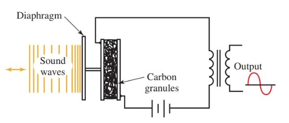
Figure 10. In a carbon microphone, sound waves change the resistance of the circuit.
Sound waves strike the diaphragm (button) and cause the carbon granules to be compressed or pushed together. This varies the resistance of the carbon.
Varying resistance causes a varying current to flow through the carbon button and the transformer primary. The output is a current that varies at the same frequency as the sound waves acting on the diaphragm.
The carbon microphone is a very sensitive device. It has a frequency response up to about 4000 Hz. This is useful for voice communication, but not for the reproduction of music. It provides a good response for its intended frequencies. A carbon microphone is non-directional, which means it will pick up sound from all directions.
Crystal microphone
The second type of microphone uses the piezoelectric effect of certain crystals. It is called a crystal microphone. When sound waves strike a diaphragm, mechanical pressure is transferred to the crystal. The flexing or bending of the crystal creates a small voltage between its surfaces. This voltage is the same frequency and relative amplitude as the sound wave, Figure 11.
Crystal microphones have a frequency response up to 10,000 Hz. They are sensitive to shock and vibration. They should be handled with care.
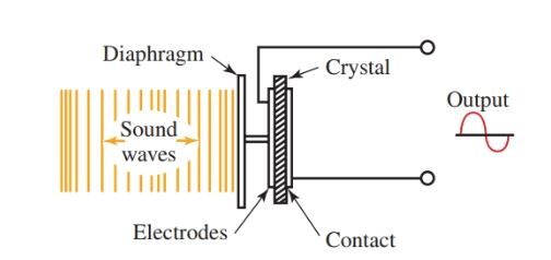
Figure 11. Mechanical pressure is used to produce electrical energy. The crystal microphone takes advantage of the piezoelectric effect.
Dynamic microphone
A dynamic microphone, or moving coil microphone, is sketched in Figure 12. As sound waves strike the diaphragm, they cause the voice coil to move in and out. The voice coil is surrounded by a fixed magnetic field.
When the coil moves, a voltage is induced in the coil (Faraday’s discovery). This induced voltage causes current to flow at a frequency and amplitude similar to the sound wave causing the motion. It has a frequency response up to 9000 Hz. It is directional and requires no outside voltage for operation.
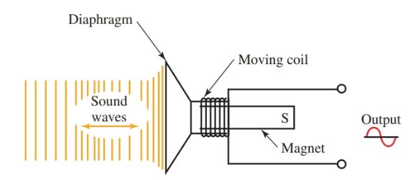
Figure 12. Dynamic microphone. Electrical audio waves are produced by a coil moving in a magnetic field.
Condenser microphone
A condenser microphone operates on the principle of capacitance. It is similar in construction to a capacitor, consisting of two plates separated by air.
One plate is rigid while the other is moveable. As sound waves strike the movable plate, the distance between the two plates will vary, varying the capacitance of the microphone.
The varying capacitance of the microphone causes a reproduction of the audio signal similar in frequency and amplitude. The condenser microphone is very sensitive when compared to other types of microphones.
Velocity Microphone
A high-quality microphone, called a velocity microphone, is made by suspending a corrugated ribbon of metal in a magnetic field.
Sound waves directly striking the ribbon cause the ribbon to vibrate. As the ribbon cuts the magnetic field, a voltage is induced.
Proper connections at the ends of the ribbon bring the voltage out to terminals. This voltage varies according to the frequency and amplitude of the incoming sound waves.
The velocity microphone is a somewhat delicate microphone with a response above 12,000 Hz. When using this microphone, the speaker must speak across its face or stand about 18 inches away. Otherwise, a “booming” effect is created.
Modulation
When you turn on the radio or TV, you expect to hear music and voices you understand. The signals of the CW transmitter mean nothing to the average person.
To make an understandable message, an audio wave is combined, or superimposed, on a carrier wave. See Figure 13.
The process of combining an audio wave with a carrier wave is called modulation.
Sound waves are converted by microphones into electrical waves, amplified, and then combined with the CW radio wave.
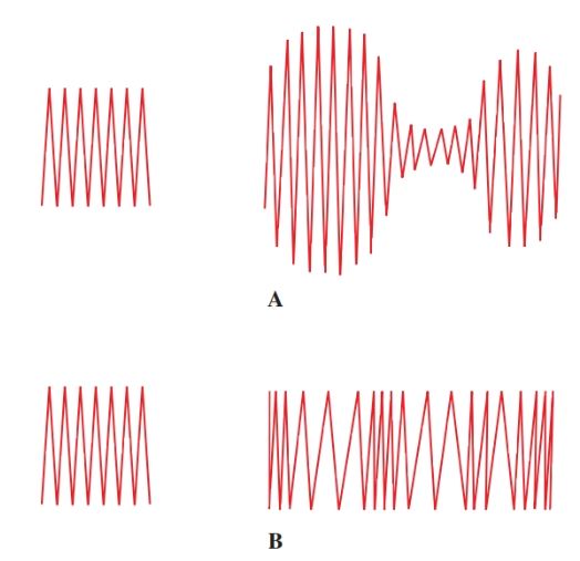
Figure 13. Carrier waves and resulting modulated waves. A–Amplitude modulation, or AM. B–Frequency modulation, or FM.
Amplitude modulation occurs when the amplitude of the CW radio wave is made to vary at an audio frequency rate. Amplitude modulation is referred to as AM.
In a second method, the radio wave frequency is made to vary at an audio frequency rate. This is called frequency modulation or FM.
Part A shows the modulation of the amplitude of a carrier wave. Part B shows the modulation of the frequency of a carrier wave.
Radio Transmitter and Receiver Key Takeaways
Understanding how a radio transmitter and receiver work is essential for anyone interested in wireless communication. A radio transmitter and receiver operate together to send and capture electromagnetic signals, enabling communication over long distances. Whether used in walkie-talkies, mobile phones, or satellites, the efficiency of a radio transmitter and receiver greatly affects the clarity and strength of the message transmitted. Engineers constantly refine the design of the radio transmitter and receiver to improve range, reduce interference, and ensure reliability. Learning the basics of a radio transmitter and receiver can open doors to exciting careers in electronics and telecommunication.