The article discusses the concept and working principles of Zero Voltage Switching (ZVS), a technique in power electronics aimed at minimizing switching losses and electromagnetic interference. It also covers ZVS applications, advantages, limitations, and components involved in implementing this method, particularly in heating control systems.
Definition
Zero Voltage Switching (ZVS) means that the power to the load (heater or cooler or other device) is switched on or off only when the output voltage is zero volts.
A major disadvantage of phase control as a means of controlling load power is the RFI generated when the thyristors are triggered into the on state.
The RFI will both radiate into the surrounding atmosphere and propagate back into the supply system. The RFI generated is particularly bad where:
- The load current is high
- The trigger angle of the thyristors is around 90°.
Supply authorities usually require RFI suppression equipment to be installed. In cases where the load current is moderately high, only low cost components are required. In high load current situations, RFI suppression equipment can be expensive.
For some load types, such as illumination control, phase control is the only viable option to control the load power. Heating elements, however, are ideally suited to on/off-type control. This is due to the high ‘thermal inertia’ of heating elements, particularly elements in large heating appliances and equipment.
Zero Voltage Switching Operation
The ZVS controls the load in a manner similar to the thermostat and simmerstat but the relative on/off times are measured in cycles.
The zero voltage switch is designed to always switch the thyristors (triacs or SCRs) as close as possible to the time when the supply voltage waveform crosses the zero line, or passes through zero. If a thyristor is triggered at the zero crossing, the RFI generated will be almost negligible and this particular disadvantage of phase control is overcome.
Control over average load power is achieved by switching the load on in bursts. For example, a low level of load power may be achieved by switching the thyristor on for five cycles and off for twenty cycles.
A medium level of power may be achieved by a cycle of on for ten cycles and off for ten cycles. This concept is displayed in the waveforms in Figure 1.
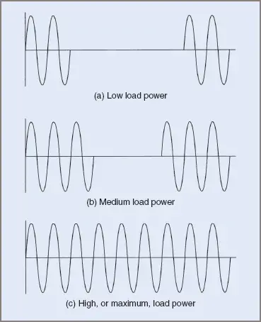
Figure 1 Zero voltage switching load voltage waveforms
In each of the above cases, a trigger pulse must be supplied at precisely the time the supply voltage passes through zero, both in a positive and in a negative direction.
A zero voltage switch consists of:
- An input, or control circuit. This is the circuit that actually controls the switching of the thyristors. It may consist of a simple on/off switch such as a thermostat or a resistance bridge, using thermistors to provide ‘proportional’ control over temperature.
- A zero-crossing detector. This circuit determines the precise time at which the trigger pulses are delivered to the thyristors.
- A pulse generator. This circuit actually generates the trigger pulse for the thyristor.
Zero voltage switches may be made from:
- Discrete components. The method is obsolete and now rarely used.
- Integrated circuits (ICs) specifically designed for this purpose.
The major application of a ZVS is in the control of heating loads. Owing to the high thermal inertia of most heating elements, the burst firing of the thyristors controlling the load will have no adverse effect on the load.
A ZVS is not suited to applications such as motor speed control, owing to the pulsating nature of the motor torque at low speeds, or to illumination control, owing to the pulsating nature of the illumination output from lamps at low settings. In the case of incandescent lamps, this would appear as an annoying flicker in the lamps.
A ZVS can also be used in situations where simple on/off control is required. A device known as a solid state relay (SSR) has been developed for this purpose. An SSR consists of the main thyristor and the zero-crossing controller.
Zero-Crossing Switch
A number of integrated circuits have been developed to incorporate all the necessary features of a zero-crossing switch. One of the simpler ICs is the Fairchild μA742. A typical connection diagram is shown in Figure 2.
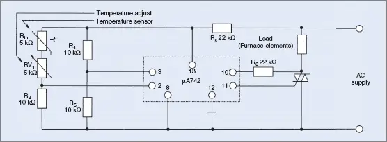
Figure 2 Integrated circuit zero-crossing switch
Resistors R2, R4 and R5, together with RV1 and Rth form a bridge circuit. The voltage at pin 3 is fixed and the voltage at pin 2 will vary as the temperature varies. If the voltage at pin 3 exceeds the voltage at pin 2, trigger pulses will be supplied to the triac. If the voltage at pin 3 is less than the voltage at pin 2, the trigger pulses will be inhibited and the triac will not turn on.
The trigger pulses will be supplied to the triac as the supply voltage passes through zero. The thyristor is usually triggered on as the supply changes from negative to positive and will be retriggered in the next negative half-cycle. This ensures that the load is always supplied with complete cycles, rather than half-cycles that result in a DC component.
Resistor Rth is an NTC thermistor. Its resistance will decrease as temperature increases. This feature, and the setting on RV1, provides the variation in voltage at pin 2. As temperature increases, this voltage increases. When the set temperature is reached, the voltage at pin 2 exceeds that at pin 3 and the triac turns off.
As the temperature then decreases, the resistance of Rth increases, causing the voltage at pin 2 to decrease. When this voltage is less than that at pin 3, the triac turns back on, re-energizing the elements. This form of control is similar to a thermostat in that it is on/off control. The temperature variation or differential will be smaller than that provided by a thermostat.
The actual on and off times for the thyristor, for a given temperature setting, will depend on the rate at which the measured temperature increases and decreases.
The manner in which temperatures might vary is shown in Figure 3.
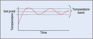
Figure 3 Temperature variations
In some applications the temperature should not vary from the set point by more than one or two degrees (or even less in some specialist applications). An example is a furnace used for case hardening or enameling operations. In these cases ‘proportional control’ is used. This results in much greater accuracy, with the temperature varying within a much smaller band.
To achieve proportional control, an ‘anticipatory’ function is built into the control of the ZVS. This allows the controller to anticipate changes in temperature and actually switches the triac on or off sooner than is the case in the circuit in Figure 2. This anticipatory function would be achieved by modulating the voltage at pin 2. This modulation could be derived from a relaxation oscillator such as a PUT oscillator.
The manner in which the temperature varies in a proportional controller is shown in Figure 4.
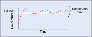
Figure 4 Temperature variations—proportional control
Key takeaways of Zero Voltage Switching (ZVS)
- Zero voltage switching (ZVS) is a technique used in power electronics to minimize switching losses and improve the efficiency of switching circuits.
- The main idea behind ZVS is to ensure that the voltage across the switching device, such as a transistor or a diode, becomes zero before it is turned on or off.
- By achieving zero voltage across the device during switching, ZVS reduces switching losses, which results in improved energy efficiency and reduced heat generation.
- ZVS is commonly used in high-frequency switching applications, such as in power converters, inverters, and resonant converters.
- The benefits of ZVS include reduced power losses, improved reliability, and enhanced overall performance of power electronic systems.
- ZVS can help minimize electromagnetic interference (EMI) and noise generated during switching operations.
- However, implementing ZVS requires careful design considerations, including the selection of appropriate components, control techniques, and circuit topologies.
- Overall, ZVS is a valuable technique in power electronics that enables efficient and reliable operation of high-frequency switching circuits, contributing to improved energy efficiency, and reduced environmental impact.
Zero Voltage Switching FAQs
What is zero voltage switching (ZVS)?
Zero voltage switching (ZVS) is a technique used in power electronics to minimize switching losses by ensuring that the voltage across the switching device becomes zero before it is turned on or off.
Why is ZVS important in power electronics?
ZVS is important in power electronics because it reduces switching losses, improves energy efficiency, and minimizes heat generation in switching circuits. It also helps to reduce electromagnetic interference (EMI) and noise.
How does ZVS achieve zero voltage across the switching device?
ZVS achieves zero voltage across the switching device by using resonant circuits or soft-switching techniques that manipulate the circuit’s energy flow. These techniques ensure that the voltage across the device becomes zero at the moment of switching.
What are the benefits of using ZVS?
The benefits of using ZVS include reduced power losses, improved efficiency, increased reliability, and enhanced performance of power electronic systems. ZVS also helps to reduce EMI and noise, leading to better overall system operation.
What are the applications of ZVS?
ZVS is commonly used in high-frequency switching applications, such as power converters, inverters, resonant converters, and other power electronic systems where high efficiency and low switching losses are desired.
Are there any challenges in implementing ZVS?
Implementing ZVS requires careful design considerations, including appropriate component selection, control techniques, and circuit topologies. Designers must also consider factors such as voltage and current ratings, switching speeds, and parasitic elements in the circuit.
How does ZVS contribute to energy efficiency?
By reducing switching losses, ZVS improves energy efficiency by minimizing power dissipation during the switching process. This translates into reduced energy waste and lower operating costs.
Can ZVS be used in all types of power electronic systems?
ZVS can be applied in various power electronic systems, but its suitability depends on factors such as the operating frequency, power levels, and specific design requirements of the system. Each application needs to be evaluated to determine the feasibility and benefits of implementing ZVS.