This article covers Silicon-Controlled Rectifier (SCR) construction, Operation, Commutation, Characteristics, Gate Requirements, Testing, and Applications along with the relevant circuit and block diagrams.
The SCR is a silicon unilateral three-terminal thyristor. It is the most commonly used and highest power rated thyristor currently available. The SCR is available in current ratings from around 1.0 A up to values in excess of 1000 A, and voltage ratings up to 5 kV.
The device performs in much the same manner as a p–n diode; that is, it will allow a current to flow in one direction, and it will block current in the other direction. The major difference is that forward conduction can be controlled in the SCR. Conduction is controlled by passing current through the gate terminal.
The SCR symbol is shown in Figure 1.

Figure 1 SCR Standard symbol
SCRs are produced in a variety of case styles, largely depending on the SCR ratings. Some case styles are shown in Figure 2.
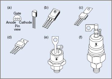
Figure 2 SCR case styles
Larger sized SCRs are manufactured in the ‘hocky-puck’ configuration. These are mounted on heat sinks to remove the excess heat produced during high current operation.
Figure 3 shows two hocky-pucks, two SCRs and two matching diodes mounted on water-cooled heat sinks. A ‘double A’ battery is included in the photo for size comparison.
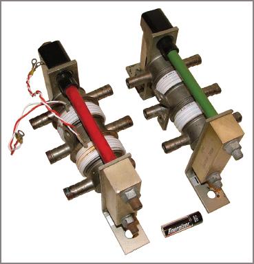
Figure 3 Hockey-puck SCRs and diodes on water-cooled heat sinks
Silicon-Controlled Rectifier Construction
The SCR is a four-layer silicon device, the layers being alternately p- and n-type semiconductor materials. This structure is referred to as p–n–p–n. Three semiconductor junctions are therefore formed in the device. Figure 4 overleaf is a representation of the layer construction in an SCR.
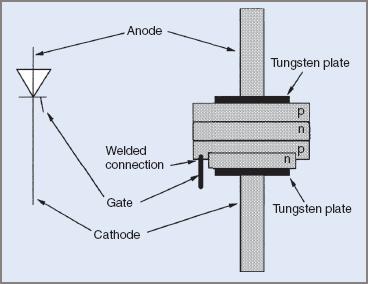
Figure 4 SCR layer construction
When the device itself is forward biased, that is, anode positive with respect to the cathode, two of the junctions will be forward biased, while the third is reverse biased. It is this reverse biased junction that allows the SCR to block anode current until gate current flows. The actual size of the silicon wafer will be varied at the time of manufacture to achieve required on state voltage and current ratings. The higher the power handling capabilities of the SCR, the larger is the wafer.
While an SCR is essentially a three-terminal device, some SCRs may appear to have only two terminals. This is due to either the anode or the cathode being connected to the case.
Some larger industrial SCRs may also appear to have four terminals. This is due to the provision of a ‘gate reference’ lead. This lead is connected to the cathode and twisted together with the actual gate lead. This minimizes the possibility of induced voltages in the gate lead causing incorrect triggering.
Silicon-Controlled Rectifier Operation
The SCR will block forward current until it is triggered into the on state by a trigger pulse. This is the normal mode of operation of an SCR. Like a p–n diode, an SCR must be forward biased to allow anode current (forward current) to flow. This means that the anode must be positive with respect to the cathode.
An SCR will switch from the off state to the on state if the forward voltage is excessive. The voltage that causes the SCR to switch from the off state to the on state is called the ‘forward break-over voltage’ (VBR). This mode of operation is not normally used as there is no real control over the SCR. This break-over voltage causes the SCR to turn on as it overcomes the reverse biased junction in the device.
The normal mode of operation is to control conduction with the gate current. Current is passed from gate to cathode. This means that the gate–cathode junction must be forward biased; that is, the gate is positive with respect to the cathode.
Consider the circuit in Figure 5. If the gate switch (S1) is open no gate current flows, therefore the SCR will not be triggered into the on state (provided that the anode voltage does not exceed the break-over voltage rating of the device).
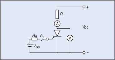
Figure 5 SCR operation
If S1 is closed, a small gate current flows. This will cause the SCR to switch to the on state and anode current will flow. Once the SCR has turned on, and provided the anode current is high enough, the gate current can be turned off and the SCR will continue to conduct. It now acts just like a p–n diode.
The forward voltage drop is relatively constant and has a nominal value of 0.6 V. In practice this value will be found to be nearer 1.0 V and may be as high as 2.0 V for very high current SCRs.
In some cases it might be found that the SCR turns back off when the gate current is removed. This means that the SCR has not ‘latched on’ properly.
For an SCR to latch on, the anode current must rise to a value known as the ‘latching current’. Once this value is exceeded the SCR will latch on and continue to conduct, even when the gate current is removed.
For the SCR to turn off, the anode current must be reduced to near zero. If the anode current falls below a value known as the ‘holding current’ it will relax back to the off state. The processes involved in reducing the anode current to this value are discussed in Section 10.2.3.
The holding and latching currents for a particular SCR are always very small values when compared with the anode current rating. The latching current is slightly higher than the holding current. For example, a C122E SCR has the following current ratings:
- anode current—8.0 A
- latching current—25 mA
- holding current—20 mA.
The reverse operation of an SCR is identical to that of a p–n diode. It will block current until breakdown occurs. This is caused by the reverse voltage exceeding the peak reverse voltage (PRV) rating of the device.
The forward operation of an SCR may be demonstrated with an SCR and an analogue ohmmeter (see Figure 6):
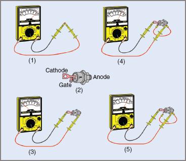
Figure 6 Steps in the operation of the SCR
1. Switch the ohmmeter to the Ω × 1 range and short the leads together to zero the reading. In carrying out this test, remember than an analogue multimeter will reverse the polarity of its terminals when switched to an ohms range. To avoid confusion, connect a red lead into the terminal marked negative and a black lead into the terminal marked positive. Then consider the red lead to be positive and the black lead to be negative.
2. Identify the lead configuration for the SCR using the manufacturer’s data sheets.
3. Connect the positive lead to the anode and the negative lead to the cathode of the SCR. Observe the reading. This reading should be high (near infinity) because the SCR should be in a forward blocking mode.
4. Connect a second positive lead from the multimeter to the gate terminal and observe the effect. The reading should fall to a low value (around 20 Ω).
5. Remove the lead from the gate terminal and observe the effect. The reading should remain low as the SCR should be latched on.
It is important to appreciate that this test is not reliable on high current SCRs because the ohmmeter might not be capable of delivering sufficient current to cause the SCR to latch on. Similar tests can be conducted using a DC supply and a suitable load.
From this examination of the operation of an SCR, it should be noted that to cause an SCR to switch from the off state to the on state, and remain in the on state, the following conditions must be satisfied:
- the SCR must be forward biased
- a pulse of current must flow from the gate to the cathode
- the anode current must rise to a level above the latching current to allow the SCR to latch into the on state
- the anode current must remain above the holding current to remain in the on state.
Silicon-Controlled Rectifier Commutation
The process of causing an SCR to turn off is known as ‘commutation’. To commutate an SCR, the anode current must be reduced to a value below the holding current. Commutation may be forced in several ways, for example:
1. Reduce or disconnect the supply voltage—this method is not practical in most situations.
2. Momentarily short the anode and cathode terminals of the SCR—this method would be dangerous on high current and/or high voltage circuits. It is not practical in most situations.
3. Reverse bias the SCR and inject a short duration pulse of current from cathode to anode—this is the most successful and widely used method of providing forced commutation of an SCR. It may be achieved by providing auxiliary circuits to connect a charged capacitor or an external pulse across the SCR to cause commutation.
When an SCR is connected to an AC supply to provide controlled rectification or control over an AC load, the anode current will fall to zero as the AC supply voltage falls to zero. When the supply reverses, the SCR will be reverse biased. This means that the SCR is commutated by the AC supply voltage and is known as ‘AC line commutation’.
SCR Characteristics and Ratings
Typical forward and reverse characteristics of an SCR are shown in Figure 7.
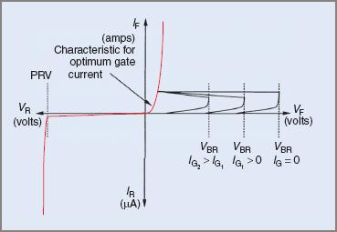
Figure 7 SCR forward and reverse characteristics curve
Like many other electronic components, an SCR has many electrical ratings. The ratings that are the most significant in a practical situation, particularly for component replacement, are:
1. Peak reverse voltage (PRV)—the maximum peak value of voltage that the SCR can withstand continuously while reverse biased.
2. Forward break-over voltage (VBR)—the maximum value of a forward voltage that can be applied to the SCR, while forward biased, without causing the SCR to switch to the on state.
3. Average forward current (IT(av))—the maximum average forward anode current that the SCR can carry. To carry this value of current without damage to the SCR it may be necessary to mount the SCR on a heat sink to dissipate the heat developed in the junctions in the device.
4. Holding current (IH)—the minimum anode current that will support conduction in the SCR. If the anode current falls below this value, the SCR will switch from the on to the off state.
5. Latching current (IL)—the minimum anode current that will cause the SCR to latch into the on state. If the anode current does not rise above this value when triggered on by the gate current, the SCR will relax back to the off state when the gate current is removed.
6. Dv/dt—the maximum rate of rise of anode voltage that the SCR can withstand when turned off, without switching back to the on state. This value is normally measured in volts per microsecond
7. Di/dt—the maximum rate of rise of anode current that is permitted in the SCR when switched from the off to the on state. If the anode current rises too quickly the current density in the silicon wafer might be too high.
8. Maximum reverse gate voltage (VRGM)—a similar quantity to the PRV rating of the SCR, but applies to the gate–cathode junction. This value is the maximum reverse voltage that may be applied to the gate–cathode junction. The value is usually significantly lower than the PRV rating of the SCR.
9. Maximum on state voltage (VT)—the maximum forward voltage drop that may be expected when the SCR is in the on state.
To obtain all necessary information relating to a particular SCR it may be necessary to refer to the manufacturer’s data sheets. Technicians and tradespeople working in situations where thyristor devices are used might find it useful to obtain a full set of data sheets from the manufacturer.
Silicon-Controlled Rectifier Gate Requirements
To ensure accurate and reliable triggering of SCRs, the trigger pulses must satisfy certain requirements as follows:
- The gate current and voltage must be high enough to trigger the SCR.
- The gate current and voltage must not be high enough to cause damage to the gate–cathode junction.
- The gate pulse must be applied for a period that allows the SCR to turn fully on.
As the gate current in an SCR increases, the voltage required to cause the SCR to break over into conduction decreases. The sensitivity of an SCR also increases with an increase in temperature. Figure 8 shows the relationship between gate current and break-over voltage.
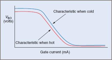
Figure 8 Effect of gate on SCR break-over voltage
Not only are the magnitudes of the gate current and voltage important, but also the actual shape and the duration of the pulse.
A gate current pulse should have a very fast rise time to allow conduction to spread throughout the silicon wafer as quickly as possible. This allows the SCR to turn on more quickly. Ideally a gate current pulse should have a rise time of less than 1 μs.
The gate current pulse should be of sufficient duration to allow the turn on process to be completed. The turn on process is complete when the SCR is latched on. In a simple resistive circuit this might take only a few microseconds, while in an inductive circuit the process may take longer.
To ensure that an SCR turns on fully before the gate current is removed, the duration of the gate should be around 50 μs to 200 μs.
The amplitude and duration of the gate pulse will depend on the type of SCR and the nature of the load. Figure 9 shows a typical gate pulse for an SCR.
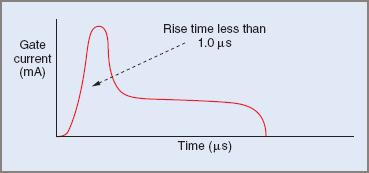
Figure 9 Typical SCR gate current pulse
In some cases, where the load is highly inductive it is necessary to have a ‘train of pulses’ rather than a one-shot pulse. This is to ensure that the SCR turns on and latches before the gate current is removed. A ‘pulse train’ consists of a series of single pulses of around 20 μs in duration with a delay of about 100 μs between each pulse.
The switching characteristics of SCRs make them ideal for many applications. An SCR can be turned on and off very quickly. SCRs are classified according to their turn-on and turn-off times. They will be classified as either:
- phase control SCRs—typical turn-on time 20 μs, typical turn-off time 40 μs
- inverter SCRs—typical turn-on time 10 μs, typical turn-off time 20 μs.
It is important to note that the time taken for an SCR to turn on or off can be affected by the characteristics of the load. Switching times are longer when the load is highly inductive than when the load is resistive.
Cooling and Protection
While an Silicon-Controlled Rectifier presents a cost-effective means of controlling power, some high current SCRs are very expensive and can cost several hundred dollars each. It is therefore worth investing a reasonable sum of money in components or devices to protect the SCR.
SCRs require protection against:
- excessive current (short-circuit protection)
- rapidly rising currents
- rapidly rising forward voltages
- excessive junction temperature.
1. Short-circuit protection—special fuses are installed in series with the SCR. These fuses can limit the prospective fault current as well as interrupt the supply. They are a variation of the normal HRC fuse. They are sometimes called semiconductor fuses or amp trap fuses.
2. Rapidly rising current (di/dt)—if the anode current rises too quickly, the current density in the silicon wafer might become too high and damage the SCR, even when the actual value of current has not exceeded the current rating of the SCR. To minimize the chances of this occurring, an inductance is connected in series with the SCR to restrict the rate of rise of anode current when the SCR is turned on.
3. Rapidly rising forward voltages (dv/dt)—when the SCR is operating in the forward blocking mode and the anode voltage rises too quickly, the SCR may turn on, causing incorrect operation of the circuit. This usually occurs when the SCR has just been turned off. To prevent it, a resistor and a capacitor are connected in series. This series combination is connected in parallel with the SCR. The RC network is known as a ‘snubber network’ and restricts the rate of rise of forward voltage across the SCR.
4. Excessive junction temperature—even though the power dissipated in an SCR is relatively low, the junction temperature may become excessive due to the relatively small mass of the device. To prevent excessive buildup of heat, SCRs are usually mounted on a heat sink. This may be a flat piece of aluminum or an extruded aluminum heat sink with fins to improve heat dissipation. To improve heat conductivity between the device and the heat sink, a heat sink compound is often smeared between the device and the heat sink. Heat dissipation is further improved if the heat sink is black anodized aluminum. In extreme cases the heat sinks may be fan and/or liquid cooled.
The following circuit (Figure 10) shows the connection of protective devices to an SCR.
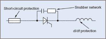
Figure 10 SCR protection circuit diagram
In some equipment using thyristor devices, other, more complex, protection methods may be employed. This may include techniques that prevent an SCR from turning on when a fault in the load is detected.
SCR Testing
A number of in-circuit tests can be carried out on an Silicon-Controlled Rectifier . These are simple tests that give an indication of the condition of an SCR. For example:
| 1. | Measure the forward voltage drop—this should be around the nominal value of 0.6 V if the SCR is on, or around the supply voltage if the SCR is off. If the SCR appears to be on, and the forward voltage drop is 0 V, the SCR is most likely short-circuited. This fault is usually caused by excessive reverse voltage. |
| 2. | Use an oscilloscope (or high impedance voltmeter) to detect the presence of trigger pulses. If no trigger pulses appear to be present, this may be due to either a faulty trigger circuit or a short-circuited gate–cathode junction. |
| 3. | If the trigger circuit is suspected to be faulty, disconnect the gate and very carefully connect a resistor between the anode and the gate (a suitable value may be around 1 kΩ). If the SCR is not faulty, this action will usually trigger it on. If this fails to turn it on, the SCR should be removed from the circuit for more thorough testing. |
Out-of-circuit testing may be carried out using a suitable analogue multimeter switched to the Ω × 1 range. Remember that most analogue multimeters reverse their polarity when switched to an ohms range.
Measure the resistance between each of the terminals with either polarity, then compare the results with a standard set. The expected resistances are specified below in Table 1.
Table 1 SCR Test Results—Serviceable SCR
|
Test polarity |
||
| Positive (+) | Negative (−) | Expected resistance |
| Anode (A) | Cathode (K) | High (infinite) |
| Cathode (K) | Anode (A) | High (infinite) |
| Anode (A) | Gate (G) | High (infinite) |
| Gate (G) | Anode (A) | High (infinite) |
| Gate (G) | Cathode (K) | Low (20 Ω) |
| Cathode (K) | Gate (G) | Medium (200 Ω) |
If an SCR appears to be satisfactory according to the resistances measured, it may be further tested to determine if it can be triggered on and latched on. For small SCRs this may be carried out using the ohmmeter. This is achieved by connecting the ohmmeter so that the Silicon-Controlled Rectifier is forward biased; anode positive, cathode negative. The reading on the ohmmeter should be near infinity.
Connect a second lead to the positive terminal of the ohmmeter (see Figure 11(b)). Connect the other end of this lead to the gate terminal of the SCR, and the reading on the ohmmeter should fall to a low value. If this gate lead is then disconnected and the ohmmeter reading remains low, it is an indication that the SCR has latched on.
If the ohmmeter reading rises to near infinity, the SCR has not latched on. The test is depicted in Figure 11(c).
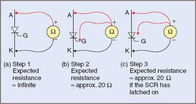
Figure 11 SCR testing
This test is a little more complex on a high current SCR. It might be necessary to use a DC power supply and a suitable load to ensure that there is sufficient current for the SCR to latch on.
In most cases the faults that occur with SCRs are very obvious. They will generally be:
- short-circuit between anode and cathode—caused by excessive reverse voltage
- open circuit between anode and cathode—caused by excessive anode current
- short-circuit between gate and cathode—caused by excessive reverse gate voltage
- open circuit between gate and cathode—caused by excessive gate current.
It should also be kept in mind that excessive forward current between anode and cathode can cause internal temperatures to rise and destroy the wafer by fusion. The result is that the Silicon-Controlled Rectifier becomes short-circuited. A similar situation can occur with excessive gate currents permanently damaging the gate–cathode junction.
SCR Applications
The Silicon-Controlled Rectifier is one of the most widely used power-control devices. It is used in countless applications in equipment designed for domestic, commercial and industrial use, including:
- controlled rectifiers
- AC controllers
- motor speed controllers
- high-output furnaces
- welding equipment
- DC/DC converters
- heating equipment
- battery chargers
- Inverters (DC/AC converters)
Silicon-Controlled Rectifier (SCR) Key Takeaways
Understanding the construction, operation, commutation, characteristics, gate requirements, testing, and applications of Silicon-Controlled Rectifier (SCR) is crucial due to their wide range of industrial and electronic applications. Silicon-Controlled Rectifier are fundamental components in power electronics, enabling efficient control of high voltages and currents in devices such as motor drives, battery chargers, light dimmers, and power regulation systems. Their ability to control conduction through gate triggering, latch into conduction states, and manage commutation effectively makes them ideal for both AC and DC circuit applications.