The article provides an overview of diac and triac, explaining their structure, functionality, and roles in controlling AC circuits. It covers their characteristic curves, switching behavior, testing methods, and practical applications in electronic devices and home appliances.
Diac and triac are two devices, usually used together for current control in AC circuits. The names are made based on “diode for AC” and “triode for AC.”
Although you now know about solid-state diode, the counterpart of that in vacuum tubes was also called diode; a tube with two elements (electrodes) inside it. That was a vacuum tube used for rectification. In conjunction with it, there were triode, tetrode, and pentode with 3, 4, and 5 electrodes inside the tube. These were used for amplification and other functions, which are performed by various transistors and other semiconductor devices nowadays.
Diac
Diac is made up of three layers of N-type and P-type semiconductors, like a transistor, but because of its doping, it does not behave as a transistor. It is more like two antiparallel diodes (two diodes in reverse direction and parallel to each other). Thus, it is a bidirectional device and conducts in both directions, suitable for AC electricity.
Nevertheless, it is not like two ordinary diodes, and conduction takes place when the applied voltage to it reaches a minimum value called breakover voltage (VBR).
Diac: Type of semiconductor device. It acts as a diode for alternating current, restricting the current until the certain voltage is reached and then it conducts normally.
Breakover voltage: Voltage below which a diac or a triac is not conducting, but when the voltage surpasses that conduction starts.
Diac Symbol
The symbol and schematic structure of a diac are shown in Figure 1. As can be observed, a diac has no cathode and the two terminals are called anode 1 and anode 2, or alternatively MT1 and MT2. MT stands for the main terminal.

Figure 1 (a) Basic structure and (b) symbols for diac.
Diac Characteristics Curve
Figure 2 shows the characteristic curve of a diac. It is a symmetrical curve, meaning that it behaves the same way for current in either direction.
The breakover voltage of diacs is around 30 V (typically 20–40 V). When the applied voltage surpasses VBR, a diac sharply conducts and the current is abruptly increased.
Later, if the current falls, conduction continues until the circuit current drops below the holding current (IH).
A diac is used for switching because it can deliver a sharp and clear signal when conduction starts. It serves for turning on the gate of a triac.
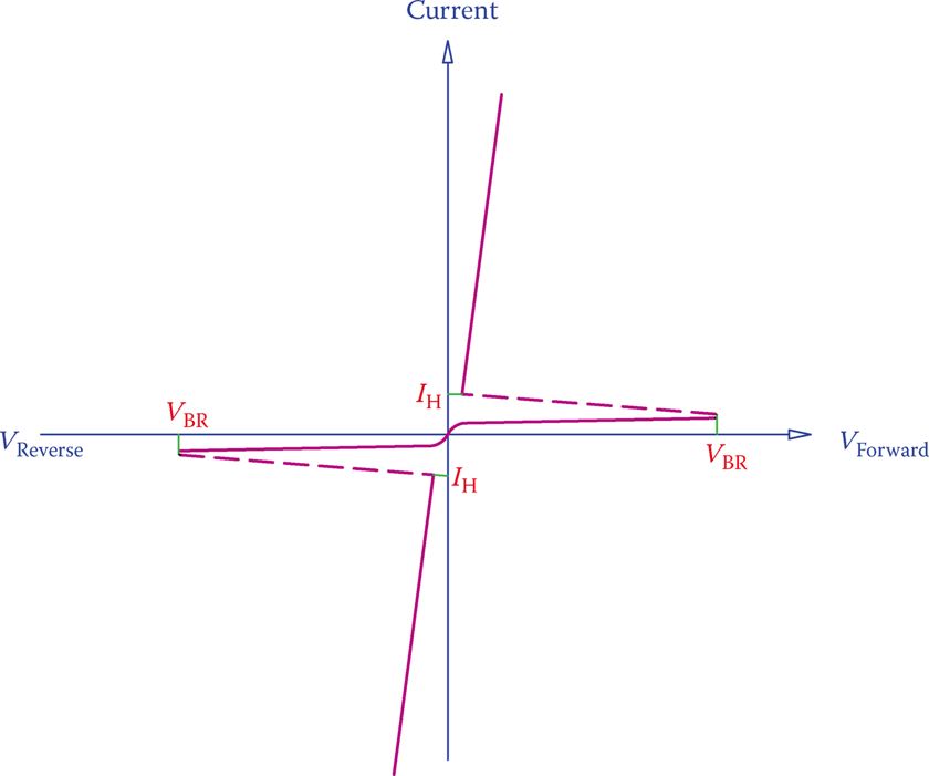
Figure 2 Diac characteristic curve.
Triac
A triac can be considered a member of a family of devices called silicon-controlled rectifier, abbreviated to SCR.
A silicon-controlled rectifier is like a diode with a gate. The gate is a control element through which the performance of a diode can be controlled. That is to say, unlike a normal diode, a silicon-controlled rectifier allows a current from its anode to its cathode only when the gate allows that.
A silicon-controlled rectifier is a four-layer PNPN semiconductor, and it has three terminals, anode, cathode, and gate.
Silicon-controlled rectifier (SCR): A family of gated diodes or transistors that can be controlled (turned on and off) through their gates.
Figure 3 illustrates the characteristic curve of a member of the SCR family. Considering only the forward bias half of the diac characteristic curve, this SCR has a similar performance except that with the current through the gate the behavior of the SCR changes.
For this device, a current flow from its anode to its cathode takes place only after the anode-cathode voltage has surpassed a minimum breakover voltage, but the breakover voltage is not fixed and can be controlled by the gate current IG.
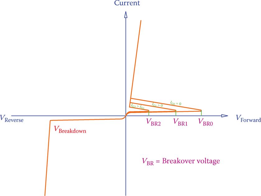
Figure 3 Characteristic curve of a silicon-controlled rectifier.
In Figure 3 the breakover voltage VBR0 is needed to start conduction in the SCR if the gate current IG is 0. For a positive IG1, the necessary voltage to start the SCR is VBR1, which is smaller than VBR0.
Similarly, if the gate current increases to IG2, the device can start conducting at a lower breakover voltage VBR2. In this way, the gate provides a means for control of the current through the SRC.
A triac is equivalent to two SCRs as shown in Figure 3 put antiparallel to each other and with their gates connected together. In this sense, it has three terminals, and it can perform in both directions, like a diac.
We may say that a triac is a diac with a gate. Its performance in each direction is similar to a controllable diac, and it is used for AC electricity. Its terminals are called MT1 and MT2, or anode 1 and anode 2, similar to a diac.
The schematics of its structure and its symbol are shown in Figure 4. As can be seen, its symbol is the same as that of a diac, with an added part for the gate.
Figure 5 shows one situation of the characteristic curve of a triac in comparison with that of a diac, which is almost symmetric for current in both directions.
In order for a triac to be turned on, either a rather high voltage must be applied to it or it must be turned on by applying a voltage to its gate. By changing the gate voltage, the minimum voltage between its two anodes (breakover voltage) to turn it on can be controlled.
Because a triac can work in either direction for current, its switching action falls into one of the following four modes: note that when A1 is connected to the mains positive terminal A2 is connected to the negative terminal and vice versa.
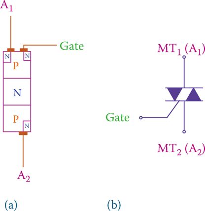
Figure 4 (a) Basic structure and (b) symbol of triac.
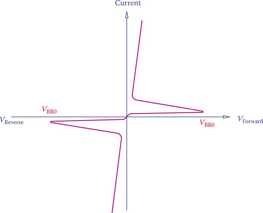
Figure 5 Characteristic curve of a triac.
- A1 is +, and the gate signal is +
- A1 is +, but gate signal is −
- A1 is −, but gate signal is +
- A1 is − and the gate signal is −
A triac can work in all cases. Only the necessary gate signal is smaller in modes 1 and 4 because the voltage difference between anode 1 and anode 2 is similar to the voltage difference between the gate and anode 2.
Current Regulation
Note that because the point of zero crossing of an AC waveform implies a zero current, a triac can turn off until the voltage across the anodes and the gate current allow conduction. In this sense, the general behavior of a triac can look as shown in Figure 6, for which the average voltage is smaller than if the current had a full waveform. This is the way that a triac can regulate the current in its circuit.
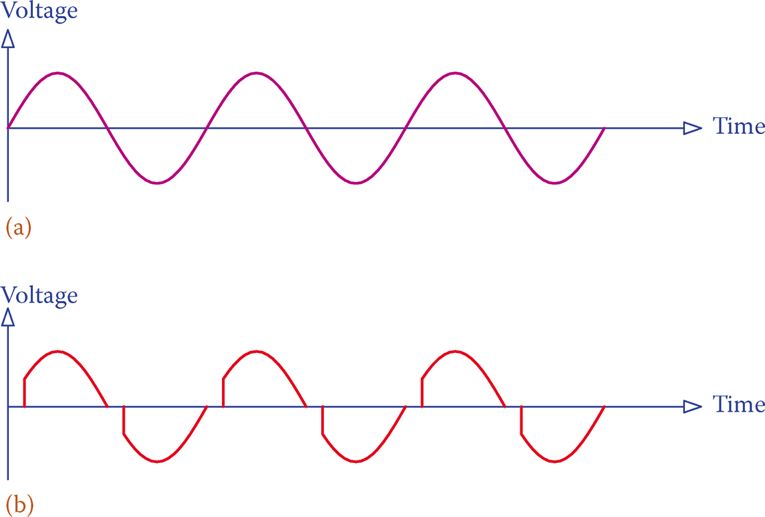
Figure 6 Effect of inserting a triac in an AC circuit. (a) Waveform without triac. (b) Waveform after triac is added.
Note that the waveform shown in Figure 6 is for a resistive load in the triac circuit. The phase shift is involved with inductive and capacitive loads.
Triacs are used for clean switching in place of electromechanical switches. They can be employed for soft starting of motors of small and medium size, particularly universal motors, lowering the inrush current in loads and many AC applications that need soft switching.
High inrush current is possible for motors because their rotor initial rpm is zero, even for heating resistors and incandescent light bulbs, because their resistance before they get hot is much lower.
Among home appliances, the vacuum cleaner, refrigerator, washing machine, and so forth have universal motors that nowadays are controlled by triacs.
A light dimmer also works with a triac, and the automatic voltage switch in many devices that must work with 120/220 V uses a triac.
There is a disadvantage with triac that they can turn on without being wanted by voltage spikes in the mains. Thus, this must be taken into account, and safety measures must be included for their usage in any electrical circuitry.
Testing a Triac
A triac can be tested by a meter. Either analog or digital meters may be used. Put the selector switch for resistance (ohm). Because a triac is an open circuit until it is turned on, a good triac shows a high resistance between its two terminals until it is triggered, when the high resistance falls to a small value or zero.
To test a triac:
- Connect anode 2 of the triac to the positive (red) lead and anode 1 to the negative (black) lead. In fact, it does not matter how you connect, as long as the gate is free. The meter should read a large resistance or OL if a digital meter is used. For an analog meter, it is recommended that first the meter is put on a large range ohm value, such as X100.
- Now you connect the gate to anode 2 (if you know which one is anode 2) or to any of the terminals. The ohmmeter reading should go down to a small value (you may want to change to a smaller range on an analog meter for more precision). The reading should stay low even if you clear the gate connection.
- Next, start over with swapping the red and black lead connections to the two anodes. The reading must show a high magnitude again.
- Make a connection between the gate and anode 2. Then the reading should fall and stay low, again, even if the gate connection is broken.
If the test results conform to the above description, the triac is good; otherwise, it is damaged. This test is good for typical triacs that do not have very sensitive gates. A small range (like X1) of an analog ohmmeter can damage a triac with very sensitive gate.
Diac & Triac Key Takeaways
Understanding diac and triac is crucial due to their vital role in controlling and regulating current in AC circuits. These semiconductor devices enable precise switching and modulation of power, making them essential in a wide range of electronic applications. From dimmer switches and motor speed controllers to household appliances like washing machines and vacuum cleaners, diac and triac provide reliable, silent, and efficient alternatives to mechanical switches.