The article covers various aspects of analog ammeter operation and types, including the utilization of d’Arsonval movements with rectifiers to measure alternating current, the role of shunts in extending the measurement range, the construction and application of multirange ammeters, the functionality of clamp-on ammeters, the use of thermocouple meters for high-frequency current measurements, and the employment of current probes and oscilloscopes for current measurement, with examples and review questions provided throughout.
The d’Arsonval movement can be used to measure alternating current if it is connected in series with a rectifier, as illustrated in Figure 1.
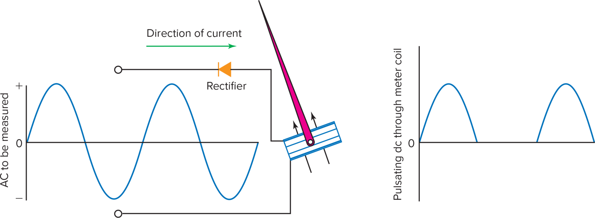
Figure 1. Principle of rectification. The rectified current flows only in one direction
Thus, the rectifier of Figure 1 allows only one-half of an AC cycle to pass. It converts alternating current to pulsating direct current. The pulsating direct current (DC) provides the constant polarity electromagnetic field required to operate a d’Arsonval meter movement. The combination of a d’Arsonval movement and a rectifier produces a rectifier-type AC meter.
Shunts
When used as an ammeter, a basic meter movement has a range equal to its full-scale deflection current. The range of an analog ammeter can be made larger by adding a shunt to the meter. A shunt is a resistor of extremely low resistance connected in parallel with the basic meter movement, as illustrated in Figure 2. Shunts are usually made from materials with very low-temperature coefficients. They are generally precision, low-tolerance (±2 percent or less) resistors.
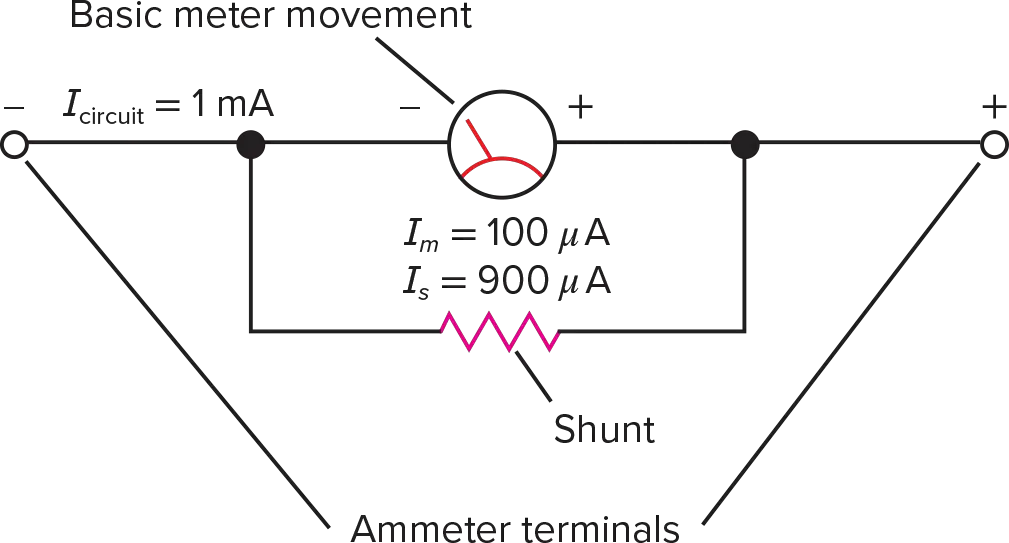
Figure 2. Ammeter with shunt. The shunt extends the range of the basic meter movement.
A shunt extends the measurement range of an ammeter by diverting the majority of the current around the meter movement. For instance, a 100 µA movement is transformed into a 1-mA ammeter by shunting 900 µA around the movement. As shown in Figure 2, the 1 mA (Icircuit) splits at the junction of the meter movement and the shunt. Then 100 µA (Im) goes through the movement and causes full-scale deflection of the pointer. The other 900 µA (Is) goes through the shunt.
Meter shunts are often enclosed in the same housing as the basic meter movement. However, for large dc currents (above 10 A), an external shunt is often used. External shunts, as shown in Figure 3, are built to handle large currents without heating up or changing resistance. Therefore, they are quite large (5 to 15 cm long).
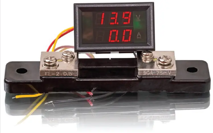
Figure 3. External shunt.
Example 1
It is desired to make a 1-A ammeter from a 1-mA, 80-Ω movement. Determine the resistance and power dissipation of the required shunt.
Given:
$$I_m=0.1A$$
$$R_m=80\Omega$$
Find:
$$R_s\ ,\ P_s$$
Known:
$$R_s=\frac{V_s}{I_s}$$
$$V_s=V_m$$
$$V_m=I_mR_m$$
$$I_s{=I}_{circuit}-I_m$$
$$P_s=I_sV_s$$
Solution:
$$I_s=1A-0.001\ A=0.999A$$
$$V_m=0.001A\times80\Omega=0.08V$$
$$R_s=\frac{0.08V}{0.999A}=0.08\Omega$$
$$P_s=0.999A\times0.08V=0.0799\ W = 79.9\ mW$$
Answer:
The shunt’s resistance must be 0.08 Ω, and its power dissipation must be 79.9 mW.
External shunts have both a current rating and a voltage rating. Current ratings ranging from 10 to several thousand amperes are common. Voltage ratings are usually either 50 or 100 mV. The voltage rating of a shunt specifies how much voltage the shunt drops when it is carrying its rated current. The rated voltage appears between the screw terminals shown on the shunt in Figure 3. When these shunts are used, leads are run from the screw terminals to a meter with a full-scale voltage range equal to the voltage rating of the shunt. The meter can be either digital or analog. Of course, the meter readout or scale will be calibrated in amperes even though it is responding to a voltage. The heavier terminals provided on some shunts are bolted into the circuit in which the current is to be measured.
Current Transformer
When measuring large values of alternating current, a current transformer (Figure 4) is used. The current transformer is essentially a toroid-core transformer that has no primary. When a current-carrying conductor is placed in the center of the current transformer, the conductor becomes the primary. An equivalent electric circuit is shown in Figure 5. The current in the conductor is stepped down by transformer action.
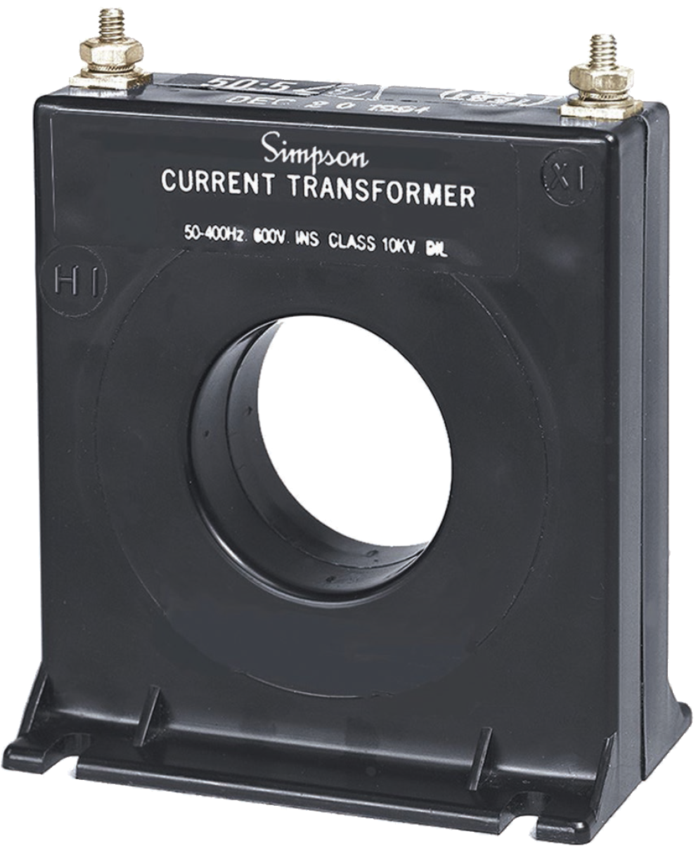
Figure 4. Current transformer.
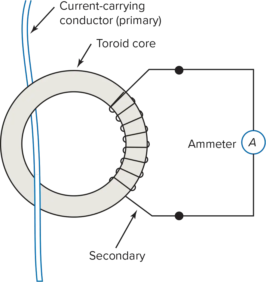
Figure 5. Current transformer principle. The conductor in which the current is being measured becomes a single-turn primary.
A current transformer may have several secondaries. This allows it to be used with a variety of ammeters, either digital or analog, having different ratings.
Multirange Ammeters
A multirange ammeter (or the ammeter section of a multimeter) is illustrated in Figure 6. It consists of a meter movement, a number of shunts, and a rotary switch. The switch is a shorting (make-before-break) type. A shorting switch is necessary so that the meter movement is shunted even while it is switching ranges. With a non-shorting switch, the meter movement would carry all the current for the instant it takes to change ranges. This instant would be sufficient time to damage or burn out the meter movement.
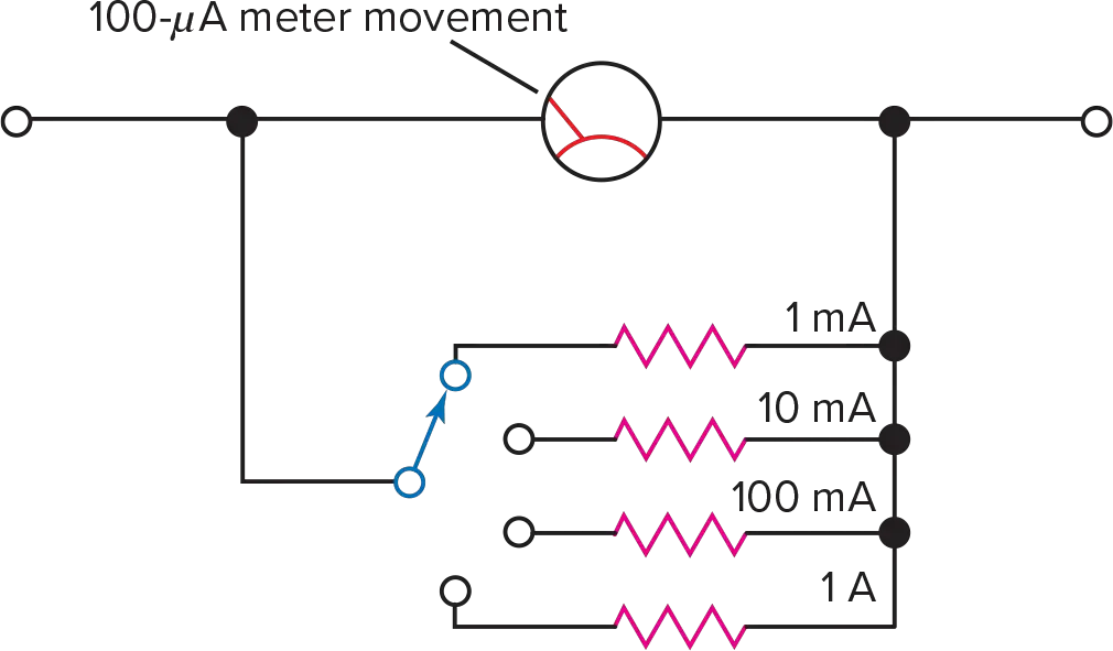
Figure 6. Multirange ammeter. Switching to a smaller shunt increases the range.
Clamp-On Ammeter
A clamp-on ammeter (also called a clamp meter) uses the same principle as the current transformer-ammeter circuit of Figure 5. However, with the clamp-on meter, the toroid core is made in two halves. The halves are hinged at one end and held together by a spring mechanism. The other end of the two halves can be separated to insert the conductor in which the current is to be measured.
A clamp-on ammeter may feature either a digital or an analog readout. The clamp-on mechanism of the clamp-on ammeter can be an accessory for use with a multimeter, or it can be a permanent part of a separate unit (clamp meter) that has its own readout, power source, and so on. Several clamp meters can also measure other quantities (voltage, resistance, and so on) by employing test leads instead of the clamp-on mechanism.
Figure 7 shows a clamp-on ammeter being used to measure current in a large conductor without interrupting the circuit. The amount of current flow is indicated on the liquid crystal display (LCD) of the clamp-on ammeter.
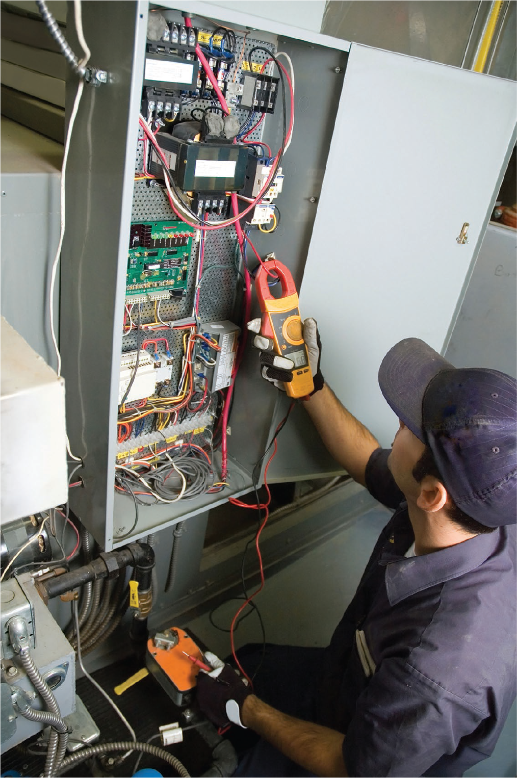
Figure 7. Clamp-on accessory for a DMM.
Thermocouple Meter
Radio-frequency currents are hard to measure with the meters discussed thus far. At these high frequencies, the inductive reactance of the meter coil is high, and the capacitive reactance of the capacitance between the turns of the coil is low. The combination of these two reactances makes some meters useless at higher frequencies. However, the thermocouple meter circumvents the reactance issue by isolating the basic meter movement from the RF currents.
The thermocouple meter, shown in Figure 8, uses a d’Arsonval meter movement connected to a thermocouple. When current flows through the meter, the resistive element heats up and increases the temperature of the thermocouple junction.
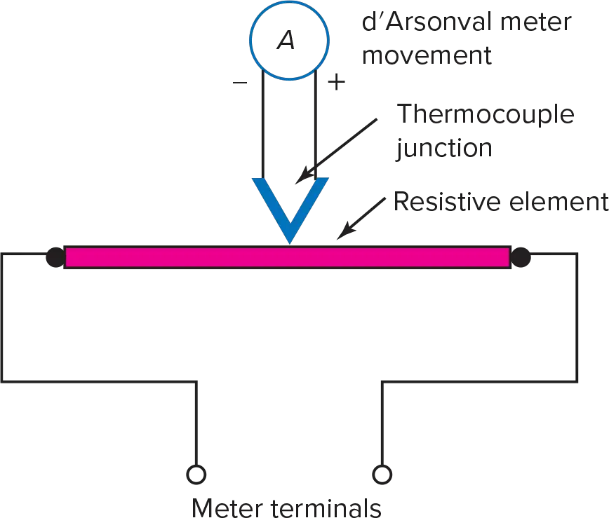
Figure 8. Thermocouple meter. The current being measured does not flow through the meter movement.
Therefore, the heated thermocouple produces a current in the meter-movement circuit. The higher the current through the resistive element, the hotter the thermocouple gets. The hotter the thermocouple, the higher the voltage it produces and the greater the current through the d’Arsonval meter movement.
Current Probe
Another technique for measuring current is to use a current probe and an oscilloscope. Current probes for oscilloscopes make it possible to measure the current in a circuit without having to break the circuit open. The probe just clamps around a conductor in the circuit. Current probes can respond to either alternating current or direct current. Probes that respond only to alternating current are known as passive probes. “Passive” means that no electronic devices are used, and no external power source is needed to operate the probe. Oscilloscope probes that can measure direct current, or both alternating and direct current, are active devices. They require an external power source to operate the Hall-effect device used to detect the level of direct current in the circuit. Active probes often use external electronic circuits to enhance the capabilities of a probe. Probes are available to accommodate currents spanning frequencies from direct current up to gigahertz and amplitudes from less than a milliampere up to 20 kA.
Analog Ammeter Review Questions
1. What type of meter movement is used in a rectifier-type meter?
2. What is a rectifier?
3. List two desirable characteristics of a shunt resistor.
4. Refer to Figure 6. How much current is carried by the shunt for the 10-mA range?
5. The meter movement shown in Figure 6 has 1200 Ω of resistance.
a. What is the resistance of the shunt for the 1-mA range?
b. What is the power used by the shunt?
6. What type of rotary switch is used in a multirange ammeter?
7. Should the internal resistance of an ammeter be as low or as high as possible?
8. When are external shunts used?
9. How are external shunts rated?
10. What is a current transformer?
11. Does the use of a clamp-on meter require interruption of the circuit in which it is used?
12. What principle is used in the clamp-on ammeter?
13. What are thermocouple meters used for?
14. A thermocouple converts______ energy into______ energy.
Answers:
- d’Arsonval movement
- a device that allows current to flow only in one direction.
- Low-temperature coefficient and low-resistance tolerance
- 9.9 mA
- (a) 133.3 Ω, (b) 108 µW
- a shorting type (make-before-break)
- low
- when measuring currents of 10 A or higher
- by current capacity and voltage drop
- a transformer used in conjunction with an ammeter to measure large values of alternating current.
- No
- the current-transformer principle
- measuring high-frequency currents
- heat, electric