The article outlines the fundamental operating principles of transformer, focusing on mutual induction, no-load and on-load conditions, and the behavior of currents and voltages in each case. It also explains phasor relationships and factors influencing the induced voltage in a transformer.
The primary and secondary windings and the magnetic core of the transformer are all stationary with respect to each other. The primary winding is connected to an alternating supply causing an alternating magnetic flux to be produced in the magnetic core (i.e. the magnitude of the flux is changing with respect to time).
The three factors required to produce an induced voltage are present: conductors, flux and relative movement. Transformer operation is based on the principle of mutual induction, that is, the changing current in the primary winding produces the changing flux in both windings, causing a back EMF in the primary winding and an induced voltage in the secondary winding, which is in fact the same as the induced EMF.
A small transformer is shown in Figure 1(a) and the standard circuit symbol for a single-phase, iron-cored transformer is shown in Figure 1(b). Note the two windings are normally wound separately and placed side by side.
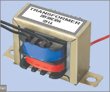
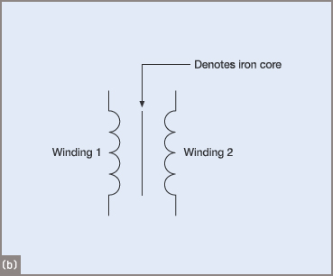
Figure 1 Transformer and drawing symbol
No-Load Conditions
Under no-load conditions, the supply voltage is applied to the highly inductive primary winding. DC would cause a larger current to flow probably burning out the transformer in a very short time. The AC current, however, produces a self-induced voltage V1′, only slightly less than the applied voltage and in opposition to the applied voltage.
The only losses are that required to produce the magnetic field and the current flowing through the resistance of the primary winding.
The no-load or excitation current is typically very small compared to the full-load current. In many cases the excitation current can be as low as 1 to 3 per cent of the full-load current.
The excitation current causes an alternating flux, called the ‘mutual flux’, to be set up in the core linking both primary and secondary windings, as shown in Figure 2. The mutual flux causes a voltage to be induced in the secondary winding—the secondary voltage V2′—but no current can flow until a load is connected.
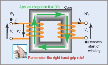
Figure 2 Non-loaded transformer
The excitation current can be resolved into two rectangular components called the energy and magnetizing components, as shown in the phasor diagram of a non-loaded transformer in Figure 3.
Parallel circuits use the voltage as the reference phasor and series circuits use the current, as in each case the reference phasor is common to all of the components in the circuit. In transformers, the mutual flux produced by the magnetizing component is common to both windings and is used as the reference phasor when drawing phasor diagrams for transformers.
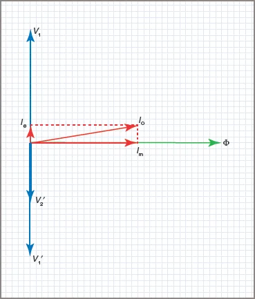
Figure 3 Phasor diagram for No-Load transformer
The phasor relationships are shown in Figure 3. The flux Φ is shown as the reference phasor, and the magnetizing component of the excitation current is in phase with it. Both Φ and Im represent the purely inductive part of the circuit and as such they will lag 90°E behind the applied voltage V1.
This means that with flux as the reference phasor, the voltage will be leading the flux by 90°E. The energy component of current Ie that represents the losses in the iron circuit and the small copper losses is resistive and will be represented by a phasor in phase with the voltage.
A wattmeter connected in the primary circuit would show power being used to cover these losses. The phasor sum of Im and Ie add up to the no-load current I0. The large angle (perhaps approaching 90°) between V1 and I0 indicates a very poor power factor for a transformer on no load.
The self-induced voltage V1′ in the primary winding, since it opposes the applied voltage, is 180°E out of phase with V1.
On-Load Conditions
When a load is applied to the secondary terminals, a secondary current I2 will flow and its magnitude and phase relationship with the secondary terminal voltage V2 is determined by the type of load.
Lenz’s law tells us that the direction of this secondary current I2 will always be such as to oppose any change in the flux Φ. In Figure 4, W1 is the primary winding with the start of the winding marked by a solid dot ‘•’.
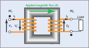
Figure 4 Loaded transformer
Assume that at a particular instant in time the primary current I1 flows from the start to the end of the winding, establishing a flux with a magnetic polarity in a clockwise direction around the iron core as shown. This flux is mutual to both coils.
The mutual flux causes a reaction current in both coils, which has the effect of opposing the establishment of the mutual flux. This can be seen as an opposing reactive flux, but the total effect is to reduce the mutual flux, thus reducing the self-induced voltage V1′ in the primary and allowing more current to flow in both the primary and secondary.
All of these events happen together. The application of a load draws a current in the secondary winding; causing a demagnetizing flux; reducing the mutual flux. The self-induced voltage in the primary decreases; the primary current increases; the mutual flux rises to its original value. In practice, the mutual flux in the iron core of a transformer effectively stays at a constant value for all loads.
An increase in secondary load current therefore causes an increase in primary line current.
The phasor diagram in Figure 5 shows the general case for a transformer on load. Assume for the purposes of the diagram that the secondary voltage is equal to the primary voltage and the connected load is inductive, so that the secondary current I2 lags behind the induced voltage V2′ by the phase angle Φ
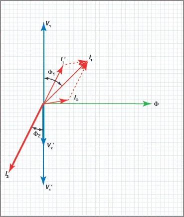
Figure 5 Phasor diagram for On-Load transformer
The equivalent current to supply this load will be the value I1′. If the transformer were 100 per cent efficient, this value of primary current would be the actual current flowing into the transformer from the supply. Since the excitation current I0 is already flowing in the primary windings to cover core losses, the total primary current will be the phasor sum of these two currents (I1′ + I0).
The phasor sum of I1′ and I0 gives the actual primary current of I1flowing at a lagging phase angle of Φ1. It should be noted that the excitation current has been enlarged for the sake of clarity and copper losses in the windings are considered negligible.
Value of Induced Voltage
The value of an induced voltage in a transformer depends on three factors: frequency, number of turns and the maximum instantaneous flux.
Provided that the current waveform, and consequently the flux distribution, is sinusoidal, the equation for the RMS value of induced voltage is given by:
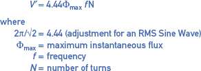
$$V^{‘}=4.44\Phi _{max}fN$$
$$where$$
$$2\pi /\sqrt{2}=4.44(\textrm{adjustment for an RMS Sine Wave})$$
$$\Phi _{max}=\textrm{maximum instantaneous flux}$$
$$f=\textrm{frequency}$$
$$N=\textrm{number of turns }$$
Since transformer cores are usually designed on the basis of permissible flux density, the above equation may be expressed as:
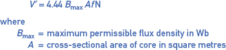
$$V^{‘}=4.44B_{max}AfN$$
$$where$$
$$B _{max}=\textrm{maximum premissible flux density in Wb}$$
$$A=\textrm{cross-sectional area of core in square metres}$$
Note: Φ = BA
Transformer Operating Principle Key Takeaways
Understanding the fundamental operating principles of transformers—including mutual induction, no-load and on-load behavior, phasor relationships, and factors affecting induced voltage—is crucial due to their wide-ranging applications in modern electrical systems. These principles form the backbone of how transformers efficiently transfer electrical energy across different voltage levels, ensuring reliable power distribution in industries, homes, and large-scale power grids. Accurate knowledge of transformer behavior under various conditions also supports the design of energy-efficient systems, fault diagnostics, and improved performance in devices such as voltage regulators, power supplies, and isolation systems.