Learn more about the basics of induction generators, including their operating principle, and explore the different types available for various applications, such as wind turbines, hydroelectric plants, and backup power systems.
An induction generator is a type of asynchronous generator, meaning the waveform that is generated is not synchronized to the rotational speed. Induction generators are widely used in wind turbines and some smaller hydroelectric installations due to their simplicity.
Another type of asynchronous generator is the permanent magnet generator. Permanent magnet generators are simple and reliable and can work at low speeds, so they are ideal for use with wind turbines.
With the advent of very strong permanent magnets, many wind turbine manufacturers are choosing low-speed permanent magnet generators for large turbines. Both induction and permanent magnet generators are covered in this section.
How Does an Induction Generator Work?
An induction generator is an asynchronous electrical machine that can function as a motor or as a generator.
In the case of an asynchronous motor, the rotor spins less than the synchronous speed of the field; as a generator, it spins faster than the synchronous speed.
An induction generator always starts as an induction motor, the most common type of motor in the world. As you know, a motor converts electrical energy into mechanical energy, and a generator does the opposite.
In an induction motor, the rotor constantly tries to keep up with a rotating field in the stator (the synchronous speed), which is created by the applied AC. The rotor slips and does not turn as fast as this rotating magnetic field; if the rotor could catch up, no torque would be generated because there would be no relative motion between the rotor and the field.
In a motor, AC that is applied to the stator is converted to mechanical rotational power that is taken from the rotor (hence, it is the armature).
Slip is the difference in speed between the rotor speed and synchronous speed of the rotating stator field; as the load increases in a motor, slip increases and the motor slows.
Maximum torque depends on the motor, but it is around 80% of synchronous speed.
Induction machines use two basic types of rotors.
A common type of rotor is the squirrel-cage rotor, which was named many years ago because of its resemblance to an exercise wheel for a pet squirrel. Figure 1 shows a squirrel-cage rotor, which has aluminum bars connected on each end for conduction.
The bars are embedded in an iron core, which produces a low-reluctance magnetic path. When AC power is applied to the stator, a voltage is induced in each rotor bar. The voltage is given by the below equation:
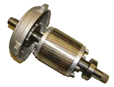
Figure 1 Squirrel-Cage Rotor Diagram. In a motor, this type of rotor is the armature; in a generator, it generates the field.
The rotor has very little resistance to the current because the conductive bars are short-circuited by the end rings; thus, a high current is developed.
This current creates magnetic poles in the rotor that are attracted to the rotating magnetic field in the stator by the induced magnetic field in the rotor.
Thus, the rotor is dragged along by the moving stator field at a speed that is nearly that of the rotating field. The rotor tries to keep up with the rotating field but cannot (if it ever did, the relative motion would be zero, and no voltage would be induced in it).
This is the normal operation of any AC induction motor, similar to that found in the motor of a household appliance such as a refrigerator or a washing machine.
Another type of rotor is the wound rotor, which is more common in a three-phase machine.
A three-phase machine usually has three windings on the rotor connected in a wye configuration and mounted on an iron core.
The windings are connected through slip rings and brushes. The wound rotor has the option of connecting external resistors into the windings to limit current during start-up; this setup is useful in larger induction machines.
For normal running, the resistors are shorted out by shorting the brushes together. The wound rotor has the advantage of being able to vary speed by varying the resistance.
It also has a higher starting torque than a squirrel-cage rotor due to the number of windings. Wound rotors are used in doubly-fed generators in wind machines.
Singly Fed Induction Generator Working
If instead of taking mechanical power from the rotor, the rotor is driven by a prime mover such as the wind, it can be moved faster than the synchronous speed and starts producing electrical power instead of consuming it. Thus, the basic induction motor becomes an induction generator.
Electrical power is now taken from the stator, which now becomes the armature. Because of this dual nature, an induction machine is sometimes referred to as a motor/generator.
All generators require a magnetic field either from some form of excitation current or from a permanent magnet.
In the case of the induction generator, after passing synchronous speed, the magnetic field is induced into the rotor from the AC that is applied to the stator.
A prime mover, such as the wind, turns the rotor faster than the synchronous speed, and power is generated, which returns power to the grid from the stator windings.
The simplest induction generators are referred to as singly fed induction generators (SFIGs), which use a squirrel cage described previously.
Because squirrel-cage induction machines look inductive, power factor correction capacitors are added to generators.
In addition, a soft-starter unit is often used to reduce inrush current during start-up. Figure 2 shows a basic SFIG system diagram used in a wind turbine.
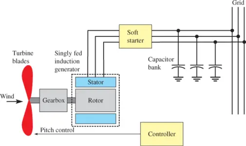
Figure 2 Basic Singly Fed Induction Generator (SFIG) Used in a Wind Turbine
Figure 3 shows a cutaway view of a small SFIG for a wind turbine. Notice that the rotor is mounted in close proximity to the stator to reduce the air gap.
The main parts are the stator, which houses the armature windings; the squirrel-cage rotor, which provides the rotating field; and the end plates, which house the bearings that support the ends of the rotor shaft.
The electrical terminals for the generator are located in the terminal box of the generator so connections can be made easily.

Figure 3 Cutaway View of an Induction Generator Diagram
As a generator, the rotor turns faster than the synchronous speed, which is called negative slip.
The synchronous speed is inversely proportional to the number of poles; if a generator has more poles, it will have a lower synchronous frequency.
For a four-pole generator with a 50 Hz output, the synchronous speed is 1,500 rpm; for a 60 Hz output, it is above 1,800 rpm. If the number of poles doubles, these synchronous speeds are halved.
To convert a slow-moving wind turbine to higher speed generally requires adding a gearbox to the system or adding many poles to the generator.
To produce power, the wind speeds need to be above the transition speed; otherwise, the motor/generator acts as a motor.
When induction generators are used in larger wind turbines, they are designed as three-phase AC machines. The AC voltage is typically increased to 12,470 V or more and connected to the grid.
Figure 4 shows a 40 kW (medium-size) three-phase induction generator for a wind turbine. The generator is 0.7 m long.
The stator coils are the armature coils on an induction generator, and the ends of these coils are connected to terminals that are accessible in a terminal box.
In a true induction machine, the rotor creates the magnetic field only through induction as it turns past the stationary coils, so no slip rings or brushes are required. This is a great advantage in cases where minimum maintenance is important.
Another advantage to induction generators is safety. If the grid goes down, the generator loses its field and stops so that it cannot send power to the grid.
The drawback to induction generators is they are less efficient than is synchronous generators.
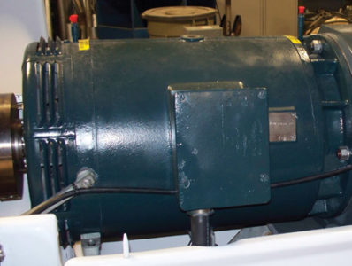
Figure 4 40-kW Three-Phase Induction Generator Diagram for a Wind Turbine
Doubly Fed Induction Generator Working and Characteristics
As in the case of singly-fed machines, doubly-fed machines can operate either as a motor or a generator. As a motor, they are useful for driving variable-speed devices such as certain tools or pumps.
The doubly fed induction generator (DFIG) is particularly useful for wind turbines and is used in many larger turbines.
A doubly fed induction generator has a wound rotor that is connected to a different source of ac than the stator. It typically has a three-phase wound rotor connected through brushes and slip rings to a secondary AC source that can be controlled for frequency, phase, and voltage.
If the secondary field is 0, then the DFIG acts like an asynchronous generator, and the output frequency depends strictly on the rotor’s rotational speed and the number of poles.
When the rotor has a secondary frequency included, the rotational speed of the magnetic field is a combination of the rotor speed and the AC fed to the rotor.
The magnetic field’s rotational speed can either be increased or decreased by changing the phasing of the AC to the rotor.
If the magnetic field due to the rotor’s applied AC rotates in the same direction as the rotor is moving, the frequency induced in the stator is higher; conversely, if it rotates in the opposite direction as the rotor is moving, the frequency induced in the stator is lower.
The bottom line is that the magnetic field’s net rotational speed can be tightly controlled to generate an exact match to the stator’s frequency and thus synchronize to the utility frequency despite variations in the rotor speed. This is a significant advantage to wind turbines because the rotor can vary to follow changing winds without affecting the output frequency for the grid.
The secondary frequency is provided directly to the rotor through slip rings and brushes without the losses experienced when the rotor receives its voltage through induction.
The controller determines the optimum characteristics of the AC for the rotor and also controls the blade pitch, which determines the speed of the rotor and optimizes power for the given conditions.
The stator is connected directly to the utility line, so it is either 50 Hz or 60 Hz, depending on what is used in that particular location. A block diagram of a typical DFIG system is shown in Figure 5.
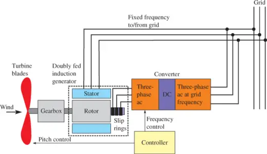
Figure 5 Doubly Fed Induction Generator Diagram. The doubly-fed induction generator can maintain an exact match of the grid frequency to return electricity to the grid.
The DFIG is more complicated than a singly fed generator and thus costs more at the outset, but it has higher overall efficiency than an SFIG and can harvest energy at various wind speeds.
It is also very useful when the amount of energy surpasses the machine’s rating intermittently. Other generators normally have to be taken offline (or be operated with reduced load) if they are exposed to conditions that exceed the design rating.
When a DFIG is used, the generator can accept the extra input energy; the generator is allowed to speed up for a short period of time, and it continues to produce the grid frequency. This continuous operation improves the overall efficiency of the generator.
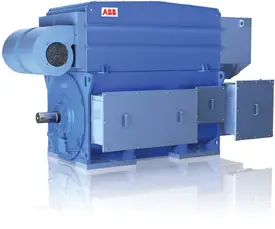
Figure 6 Vibration Testing in an Induction Generation
One of the most critical tests of any generator is balancing the generator to ensure that rotor vibration is within acceptable limits.
Testing needs to include tests of the maximum over speed. Designers need to specify the shaft stiffness and balancing requirements and test technicians verify that the generator operates within these specifications.
One of the important control factors that make the doubly fed induction generator widely used in wind turbines and microhydraulic systems is that an ac-dc-ac converter is used to control the frequency of the voltage fed to the rotor.
The slip rings and brushes in this system carry only the current for the field; some power is produced via the rotor, but it is only about 20% of the total.
Because the rotor current is small compared to the total current, the brushes can be smaller and thus have less wear.
If the doubly-fed induction generator is used with a wind turbine, it can produce power with a constant utility frequency in wind speeds from 6 mph to 50 mph. This allows the wind turbine to accept gusting winds and allows the blades to harvest the extra energy when the wind speeds are very high, which in turn improves the wind turbine’s efficiency.
If the wind turbine is very large (2 MW or larger), the control system can incorporate individual wind turbine blade adjustments and nacelle directional yaw adjustments to harvest the maximum amount of wind available.
The doubly-fed induction generator is also used in microhydrogenation and other renewable energy systems where the generator speed may be variable.
Variable-Speed Induction Generator Working
Another option for handling a variety of wind speeds is a generator configuration called a variable-speed induction generator (VSIG), which uses a large number of poles and requires no gearbox, with its associated losses and maintenance issues.
Mechanical loading in the drive train is thus reduced because the generator is completely decoupled from the grid. The configuration uses electrical or permanent magnet excitation and allows the generator to optimize power at an uncontrolled frequency.
A full-scale frequency converter performs reactive power compensation and conversion to grid-quality AC. For wind turbines, the system can take advantage of an input in wind speeds ranging from a few mph during start-up to over 40 mph winds.
The drawback is that the power electronics converter and the large multipole generator are expensive. Figure 7 shows a block diagram of the system.
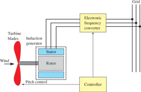
Figure 7 Variable-Speed Induction Generator Working Diagram. A variable-speed induction generator uses a full-scale electronic frequency converter to match the grid frequency.
Permanent Magnet Generator Working
The permanent magnet (PM) generator relies on a very strong permanent magnet to provide the original rotating magnetic field for the generator.
The rotor in this generator is a very strong permanent magnet that continually puts out a very strong magnetic field. The stator is made of coils of wire that are mounted in the stationary part of the generator.
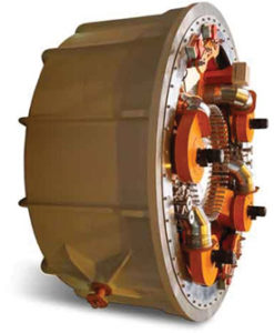
Figure 8 Cutaway View of a Magnet Low-Speed Generator Diagram
This permanent magnet low-speed generator can produce power up to 4.25 MW and can withstand overpowering for limited periods of time.
Permanent magnet generators use expensive rare earth neodymium magnets and can have either inner or outer rotors.
When the rotor begins to turn, the magnetic field cuts across the stator coils and a voltage is generated in the stator coil. Because the stator coils are in the stationary part of the generator, the permanent electrical connections at the terminal end of each coil allow voltage to be taken off the stator coils without brushes or slip rings.
The main advantage of the PM generator is its simple design (it does not require an exciter). It requires very little maintenance because it can be completely sealed, and it does not use brushes.
Figure 9 shows the internal parts of a permanent magnet generator used in a wind turbine.
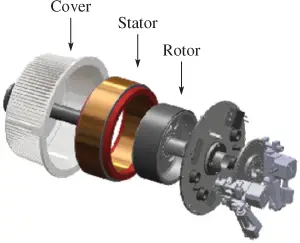
Figure 9 Permanent Magnet Generator Labeled Diagram
Early PM generators were small generators used primarily for charging batteries, or they were used with a small inverter to provide a low-power AC.
Today, PM generators are used in wind turbines of various sizes, including very large ones such as offshore turbines.
Some wind turbines are low-speed direct drive turbines that rotate between 11 and 17 rpm and produce up to 4.25 MW.
Other wind turbines that use PM generators can use one or two-stage gearboxes that turn the generator at 150 to 400 rpm and produce 3.2 MW, or they can use two or three-stage gearboxes that turn between 1,000 to 1,500 rpm and produce up to 1.6 MW.
When the PM generator is used in a wind turbine, the blade speed is not controlled, and it produces a single- or three-phase AC power at a variable voltage and frequency.
Because the PM generator’s output voltage and frequency vary with its rotational speed, a full power converter (FPC) is used to provide three-phase electricity at fixed frequency and voltage levels to match the grid.
The FPC uses transformers and robust line conditioners to ensure that the electricity meets the strict network requirements for harmonics, flicker, and fault ride-through.
Table 1 compares the generators discussed in this article on the basis of their advantages, disadvantages, and some basic characteristics.
DC Generator |
AC Induction (Asynchronous) Generator | Doubly Fed Induction Generator | Synchronous Generator with Exciter | Synchronous Generator with Permanent Magnet Rotor | Permanent Magnet Generator | |
| Advantages | No frequency control needed; output is DC | Simple design; few parts; inexpensive | Provides controlled frequency of the output voltage | Provides controlled frequency of the output voltage | Provides controlled frequency but does not need an exciter, slip rings, or brushes | Simple design; few parts; does not require dc voltage for excitation |
| Disadvantages | Brushes and commutator wear out periodically | Frequency not controlled | Needs voltage from the grid to excite the field | Needs exciter voltage and brushes and slip rings | Difficult to disassemble because of the permanent magnet | Frequency not controlled |
| Frequency control | No frequency; output is a dc voltage | Not controlled | Controlled by providing a fixed frequency to the field | Controlled when synchronized | Controlled when synchronized | Not Controlled |
| Speed of rotor | Variable | Variable | Variable | Constant | Constant | Variable |
| Brushes and slip rings | No | No, uses induction | Yes | Yes, unless permanent magnets are used for field | No, uses a permanent magnet | No, uses a permanent magnet |
| Brushes and commutator | Yes | No | No | No | No | No |
| External voltage or exciter needed | No | No | No | Yes | No | No |
Table 1 Comparison of Induction Generator Types
Key Takeaways of Induction Generator
- An induction generator is commonly used in wind turbines to convert mechanical energy from the rotating blades into electrical energy.
- Induction generators are known for their simplicity, reliability, and low maintenance requirements.
- They have the ability to self-regulate their output power, which means they can adapt to varying wind speeds without the need for complex control systems.
- Induction generators can efficiently generate electricity even at low wind speeds, making them suitable for a wide range of wind power applications. However, they have certain limitations, such as a limited ability to provide reactive power and a lack of grid synchronization capability without additional equipment.
- Overall, induction generators play a significant role in the renewable energy sector, particularly in harnessing wind power for clean and sustainable electricity generation.
Induction Generator FAQs
- What are the main parts of an asynchronous induction generator?
- How does a doubly-fed generator produce electrical power at a fixed frequency?
- What is the difference between a squirrel-cage rotor and a wound rotor?
- Name some of the applications of a variable-speed induction generator.
Answers
- The main parts of an asynchronous induction generator are a rotor (consisting of electrical loops, either wired or in the form of a squirrel cage, that is spun by a prime mover to something above the synchronous speed); a stator (which is a rotating electrical field provided by ac); and the usual bearings, fan, and case.
- A doubly-fed generator is a rotating field generator that is connected to two AC sources: one on the wound rotor and one on the stator. The rotor’s AC is supplied through slip rings and brushes from a controlled AC source that combines with the rotor speed to produce a net rotation of the field that exactly matches the stator frequency. The stator is connected to the ac utility line.
- A squirrel-cage rotor is an aluminum cage with conducting bars that are shorted together by a ring at each end. The cage surrounds an iron core that provides a path for the magnetic field. A wound rotor has wire windings instead of an aluminum cage.
- A variable-speed induction generator can be used in a wind turbine that converts the output to dc and back to grid-quality AC using an inverter. It is also useful in applications that are independent of the grid.