Learn about the synchronous motor equivalent circuit, which represents the electrical characteristics of the motor and helps analyze its performance. Additionally, explore the phasor diagram of the synchronous motor, illustrating the relationship between voltage, current, and power factor at both leading and lagging current conditions.
The equivalent circuit for one phase of a synchronous motor is shown in Figure 1. It is similar to the synchronous generator equivalent circuit, but with two differences.
First, it has been flipped to show the power system as the input to the motor, and, second, the current is referenced as positive into the motor.
The power system normally constitutes an infinite bus because the motor is much smaller than the rest of the power system. When the rotor field rotates at synchronous speed, a counter EMF (C-EMF), Ea, is induced into the armature windings. Writing a voltage loop equation yields
$\begin{matrix} {{V}_{t}}={{E}_{a}}+jI{{X}_{s}} & {} & \left( 1 \right) \\\end{matrix}$
Which can be rearranged as
$\begin{matrix} {{E}_{a}}={{V}_{t}}-jI{{X}_{s}} & {} & \left( 2 \right) \\\end{matrix}$
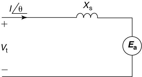
Figure 1: Per-phase equivalent circuit for a synchronous motor.
Synchronous Motor Phasor Diagram
Equation 2 is the preferred form since the terminal voltage is normally chosen as the reference phasor for purposes of drawing a phasor diagram. With a known terminal voltage, we can construct phasor diagrams for the synchronous motor, as shown in Figure 2. Figure 2(a) shows a phasor diagram for a lagging current.
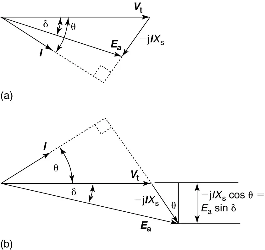
Figure 2: Phasor diagrams for a synchronous motor.
- Lagging current.
- Leading current.
Since the motor is a load, a lagging current means the motor is accepting lagging current and is thus acting like an inductive load. The voltage drop across the synchronous reactance is -jIXs. The -j operator constitutes a rotation of 90° in the clockwise direction, so the synchronous reactance voltage drop is perpendicular to the current in the direction shown.
The resultant C-EMF is found to be lagging the terminal voltage by the power angle delta (δ). From the phasor diagram in Figure 2(a) we can observe that
$\begin{matrix} {{E}_{a}}\cos \delta <{{V}_{t}} & {} & \left( 3 \right) \\\end{matrix}$
Which means the motor is operating in an under-excited condition, drawing reactive power from the infinite bus.
Figure 2(b) shows a phasor diagram for a motor operating with a leading current. Since the motor is accepting leading current, it is acting like a capacitive load. In this case, the generated voltage still lags the terminal voltage by the power angle, but the magnitude of the generated voltage is now greater than the terminal voltage, or, more specifically,
$\begin{matrix} {{E}_{a}}\cos \delta >{{V}_{t}} & {} & \left( 4 \right) \\\end{matrix}$
In this case, the motor is overexcited and provides reactive power to the infinite bus.
Synchronous motors are typically rated to deliver a certain horsepower while operating at a particular value of power factor.
The most common power factor ratings for synchronous motors are unity and 0.8. A motor rated for 0.8 power factor would obviously be larger and more expensive than one rated for unity power factor because both the armature conductors and the field conductors would have to carry more current at the lower power factor.
If operated at less than unity power factor, the synchronous motor would almost certainly operate in the leading direction.
Key Takeaways of Synchronous Motor Equivalent Circuit
The synchronous motors equivalent circuit provides a simplified representation of the motor’s electrical behavior, helping in analyzing its performance and understanding the flow of current and power.
The phasor diagram of a synchronous motor demonstrates the relationship between voltage, current, and power factor. At leading current, the motor operates in an over-excited state, while at lagging current, it operates in an under-excited state, affecting its power factor and performance.
Synchronous Motor Equivalent Circuit FAQs
What is the purpose of the synchronous motor equivalent circuit?
The synchronous motor equivalent circuit is used to model the electrical behavior of a synchronous motor, allowing engineers to analyze its performance, understand its characteristics, and calculate its parameters.
What does the phasor diagram of a synchronous motor show?
The phasor diagram of a synchronous motor illustrates the relationship between the voltage, current, and power factor of the motor. It helps in visualizing the electrical quantities and understanding the motor’s operating condition.
How does the synchronous motor behave at leading current?
At leading current, the synchronous motors operates in an overexcited state. This means that the motor’s field excitation is higher than the required value, resulting in a leading power factor. The motor can supply reactive power to the system and improve the overall power factor.
What happens when the synchronous motor operates at lagging current?
When the synchronous motors operates at lagging current, it is in an underexcited state. This means that the field excitation is lower than the required value, resulting in a lagging power factor. The motor absorbs reactive power from the system, which can decrease the overall power factor.
How does the power factor affect the performance of a synchronous motor?
The power factor of a synchronous motors indicates its ability to convert electrical power into mechanical power efficiently. A leading power factor signifies good power factor correction and the ability to supply reactive power to the system. On the other hand, a lagging power factor indicates a need for reactive power compensation. The power factor influences the motor’s efficiency, voltage regulation, and overall system stability.
Can the synchronous motor equivalent circuit and phasor diagram be used for other types of motors?
The synchronous motors equivalent circuit and phasor diagram are specific to synchronous motors, which have unique characteristics and operating principles. Other types of motors, such as induction motors or DC motors, have their own equivalent circuits and phasor diagrams tailored to their specific characteristics.