The article discusses the main types of losses in a transformer—iron losses (including eddy current and hysteresis losses) and copper losses—and explains how they affect transformer efficiency. It also covers related concepts such as flux leakage, voltage regulation, and testing methods used to measure these losses.
Iron Losses
Eddy Currents
The magnetic core of a transformer consists of many laminations of a high-grade silicon steel of a definite thickness. The power absorbed by the core of a transformer is due to eddy currents and hysteresis and is called iron losses.
When the alternating flux cuts the steel core, an EMF is induced in each lamination, causing a current (called an eddy current) to flow in the closed electrical circuit of the lamination. This eddy current flows through the resistance in each lamination, causing heat to be generated in the laminations and therefore in the core as a whole. Although eddy-current losses are effectively reduced by using laminations for the core, they are never entirely eliminated.
Hysteresis
The alternating flux also causes changes in the alignment of the magnetic domains in the magnetic core, with the magnetic polarity reversing 100 times a second. This change is energy consuming and heat is produced within the core. The energy loss is referred to as hysteresis loss, the degree of loss being dependent on the nature of the material used for the laminations.
Silicon steel has low hysteresis losses, making it suitable for electrical laminations. Figure 1 shows a comparison of two hysteresis curves for different materials. It can be seen that the silicon steel curve has a smaller area, representing a lower energy loss and reduced heat production.

Figure 1 Hysteresis curves
The total iron losses represent the power absorbed by the iron core and so are proportional to Ie, the energy component of I0 in Figure 2. The mutual flux Φ remains fairly constant from no load to full load, therefore it follows that the excitation current I0 producing that flux, and so Ie, will also be constant.
The iron losses will be constant irrespective of the load applied to the transformer. These iron losses can be obtained by measuring the power consumed on no load in what is known as a ‘no-load or open circuit test’.

Figure 2 Phasor diagram for no-load transformer
The transformer is connected as in Figure 3 to a supply at the rated voltage and frequency. The primary current on no load is usually less than 3 per cent of the full-load current, so the primary I2 R loss on no load is negligible compared with the iron loss. The wattmeter reading can then be taken as being the total iron loss of the transformer.
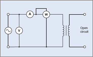
Figure 3 No-load or open-circuit test
Copper Losses
Another form of loss that occurs in a transformer is copper loss, which is the energy lost in the windings when the transformer is loaded. The resistance of each winding is relatively low, but since the power dissipated in each winding is proportional to the square of the current flowing through that winding, it follows that the copper loss is significant when the load current is high.
The total copper loss is PCu = I12 R1 + I22 R2, where R1 and R2 are the resistance values of the primary and secondary windings respectively. The copper losses are not constant, but change according to the square of the load current. The value of the losses can be obtained by performing the short-circuit test, as shown in Figure 4. The typically shaped curve of copper losses can be seen in Figure 5.
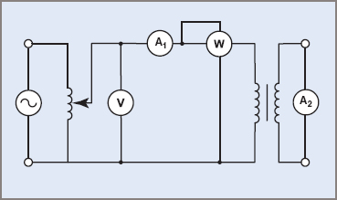
Figure 4 Transformer short-circuit test

Figure 5 Transformer Iron and Copper losses
As Figure 4 shows, the secondary winding of the transformer under test is shorted through the ammeter A2. An adjustable autotransformer is used to provide a low-voltage supply to the primary winding of the transformer on test. The output of the autotransformer is increased until the full rated current flows in the primary and secondary circuits.
The supply voltage to the transformer is low, and the flux in the iron core is also low, and so the iron losses are negligible. The power registered on the wattmeter W can be taken as the total copper losses in the transformer on full load.
Transformer Efficiency
The efficiency of any machine is expressed as:
![]()
$$\eta =output/input$$
A transformer normally has a high efficiency, therefore the difference between the output and input readings is very small (typically 1–3%) and the efficiency is usually determined from the losses.
![]()
$$\eta =output/input=output/output+losses$$
That is,
![]()
$$V_{2}I_{2}\lambda_{2}/(V_{2}I_{2}\lambda_{2}+P_{Cu}+P_{Fe}) $$
Where
- PCu = copper losses
- PFe = iron losses
Assuming the output voltage V2 remains constant, the only variables affecting the efficiency of a transformer are load current and power factor.
Flux Leakage
It has been assumed so far that all of the primary winding flux was magnetically linked with the secondary winding, thus creating a mutual flux that coupled both windings perfectly.
In practice a small portion of the primary flux passes through the air gap and does not cut the secondary conductors. This flux is called the primary leakage flux and is shown as Φ1 in Figure 6.
The leakage flux helps in producing the self-induced voltage V1′ in the primary winding but, in bypassing the secondary winding, plays no part in producing the voltage V2, which is accordingly reduced slightly below the theoretical value.
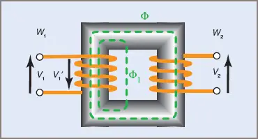
Figure 6 Primary leakage flux
When the transformer is on load, the secondary current I2 sets up a demagnetizing flux opposing the mutual flux. Some of this secondary flux also passes through the air gap and is called the secondary leakage flux (indicated as Φ2 in Figure 7).
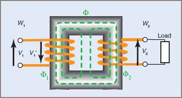
Figure 7 Secondary leakage flux
The primary and secondary leakage fluxes both induce voltages in their respective windings and cause inductive reactance to be set up. As the load current increases, the leakage flux—and so the inductive reactance—increases. This inductive reactance and the winding resistance cause voltage drops on load, as shown in Figure 8 overleaf.

Figure 8 Transformer load curves
In most transformer applications, leakage flux is a disadvantage and various methods are used to reduce it to a minimum. An arrangement such as the one in Figure 7, with the primary and secondary windings on separate limbs, is a poor design and is rarely used in practice.
To minimize leakage flux, transformers are designed with the shortest possible magnetic core path, a low flux density in the core and a high reluctance path for the leakage flux. This is achieved by using a combination of winding arrangements and special core shapes.
Voltage Regulation
A transformer is expected to deliver a pre-determined voltage at full load. The two major losses discussed in the previous section were:
| 1. | Magnetic losses, which include leakage flux and other magnetic core losses |
| 2. | Copper losses due to winding resistance. |
Because of these losses the full-load voltage will tend to be less than the no-load voltage.
To obtain a regulation value, the primary input voltage should be maintained at its rated value and the power factor of the load must be known—the regulation value obtained is relevant only at this value of power factor for a particular transformer. The formula given is really only accurate for single-phase transformers.
Voltage regulation of a transformer can be expressed as a percentage of its full-load voltage:
![]()
$$\textrm{voltage regulation}=[(V_{NL}-V_{FL})/V_{FL}]\times 100\textrm{%}$$
Note that the voltages used are all secondary values. Where a formula differs from the above, it should be checked to see whether equivalent or reflected values are to be used.
Care must be exercised when using a regulation value as a basis for comparison with another transformer. Comparisons with transformers of a different load, power factor or voltage ratio are not valid.
Transformer Losses and Efficiency Key Takeaways
Understanding transformer losses and efficiency is crucial for the effective design, operation, and application of transformers in real-world electrical systems. Iron losses (including eddy current and hysteresis losses) and copper losses directly impact the energy efficiency and thermal performance of a transformer. Efficient transformer designs reduce power waste, improve reliability, and ensure stable voltage regulation across various load conditions. This is particularly important in applications such as power transmission, distribution systems, and industrial equipment, where energy savings and voltage stability are critical.