This article covers molded case circuit breaker (MCCB) working/operating principle, its different parts and their functions, and labeled circuit diagram.
A molded case circuit breaker (MCCB) is a circuit breaker that uses a molded case to house and supports its current-carrying components as well as to be a part of the insulation system. The working principle of MCCB is discussed in detail in this article.
The most common type of MCCB is the thermal-magnetic general-purpose circuit breaker. See Figure 1. MCCBs often have a thermal overcurrent trip element to provide protection against overloads, such as what is caused when a coupling is misaligned on an electric motor or an electrical device draws too much current. An instantaneous overcurrent element is also provided to protect against short circuits, such as what is caused when two wires touch or when insulation fails.
Molded Case Circuit Breaker (MCCB) Parts and Functions
MCCBs have the following primary components/parts:
- frame or case
- contact assemblies
- Arc chutes
- OCPDs
- an operating mechanism
- Terminal connections
An insulated-case circuit breaker (ICCB) is a circuit breaker that is similar in construction to an MCCB but typically uses an electronic or digital OCPD and has much higher interrupting ratings.
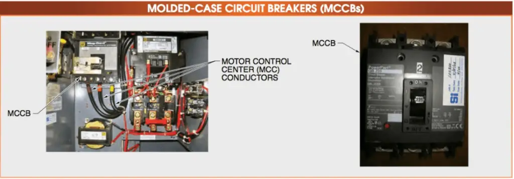
Figure 1. Molded Case Circuit Breaker (MCCB) Labeled Circuit Diagram
MCCB Frames and Cases
The frame on a Molded Case Circuit Breaker (MCCB) is an enclosed unit that surrounds and supports the other components while providing insulation. Sealed-case circuit breakers cannot be opened or serviced, except for testing, inspection, and cleaning of the outside.
Sealed-case circuit breakers can be identified in several ways: by a tarlike substance, riveted cases, or paper seals over the case screws. Opening sealed-case circuit breakers invalidate their UL listing, which can cause issues if there is a fire or other accident involving those circuit breakers.
Large-frame MCCBs and most ICCBs have replaceable OCPDs and are also known as interchangeable trip circuit breakers. Interchangeable trip circuit breakers have cases that can be opened to be serviced and maintained. OEMs can provide certain parts so that they can be renewed.
The OCPD can be replaced with an element that can be sized up to the frame rating of ICCBs and up to 80% of the frame rating of MCCBs. See Figure 2.
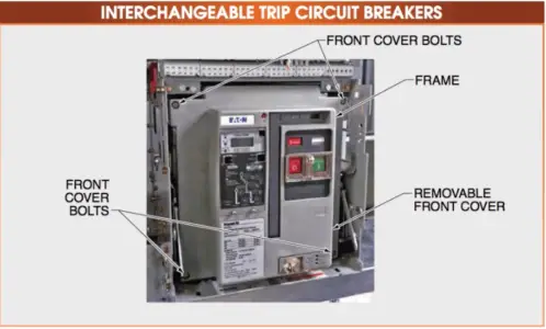
Figure 2. Interchangeable trip circuit breakers labeled circuit diagram
MCCB Contact Assemblies
The contact assemblies open and close circuits. The contacts on small MCCBs, such as branch circuit breakers used in panelboards, carry the load current and also act as arcing contacts. Large-frame circuit breakers have separate arcing contacts and main contacts.
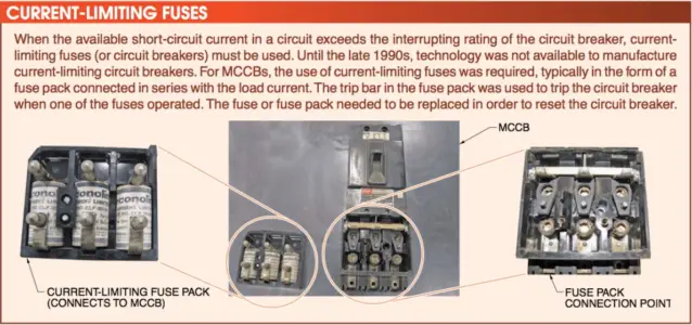
One advantage that Molded Case Circuit Breakers (MCCBs) have is that their contacts are small, light, and can interrupt an arc quickly, such as in 1-1/2 to 2 cycles. Current-limiting versions can clear a fault even quicker, in a 1⁄2 cycle or less.
Arcing contacts aid in interrupting arcs and are composed of a harder alloy than the main contacts, which are designed to carry only load current. The arcing contacts (upper) extend ahead of the main contacts (lower). As the circuit breaker closes, the arcing contacts touch (make) first. Therefore, any arc that occurs does so on the arcing contacts. The main contacts then touch immediately after the arcing contacts touch.
The main contacts are primarily composed of silver and are softer than the arcing contacts, which means that they will erode quickly if the arcing contacts are misadjusted or worn. New generation current-limiting circuit breakers differ from standard MCCBs and primarily by their contact structures.
Standard Molded Case Circuit Breakers (MCCBs) use single pivot-point mechanisms for the contacts, while current- limiting circuit breakers often use dual-pivot mechanisms. See Figure 3. The magnetic fields around each of the contacts repel and rapidly force the contacts apart. As the short-circuit current flowing through them increases, the magnetic fields become stronger, and the contacts open faster.
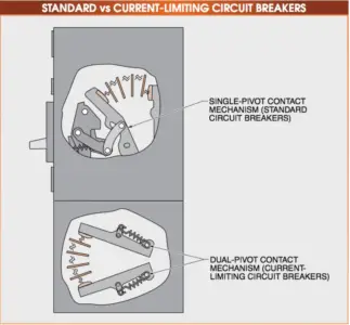
Figure 3. Standard MCCBs Vs. ICCBs
For these circuit breakers (and current-limiting fuses) to be current-limiting, the short-circuit current must be of value high enough to cause it to be in its current-limiting region. If the short-circuit current is below this value, it responds as a standard circuit breaker.
MCCB Arc Chutes
An arc is a sustained discharge of electricity across a gap in a circuit or between electrodes, usually accompanied by the electrodes (contacts) being vaporized and/or melted by the extreme heat of the arc.
An arc chute, also known as arc extinguisher, is a structure that contains arc dividers. As the contacts part, the arc is drawn between the arcing contacts. The arc rises (due to its extreme temperature) and, as it does so, is stretched by the arc dividers. This cools the arc so it can be extinguished. MCCBs use arc chutes to stretch arcs, cool them down, and extinguish them, all in 1-1⁄2 to 2 cycles. See Figure 4.
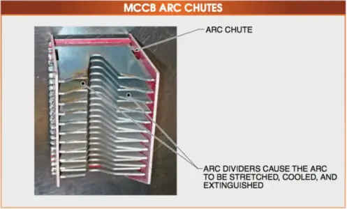
Figure 4. Molded Case Circuit Breaker (MCCB) Arc Chute Diagram
Over Current Protective Devices (OCPDs)
Small-frame MCCBs typically use thermal-magnetic OCPDs.
A thermal-magnetic OCPD is an OCPD that reacts to the heat created by the copper loss (I2R) when current passes through a conductor.
Copper loss is caused by the resistance of the conductor to a current passing through it. This loss is expressed as heat. The higher the current flow through a conductor, the more heat is created. A thermal-magnetic OCPD uses a bimetallic strip placed in the current path. The bimetallic strip is made of two metals that have different rates of expansion when heated. The bimetallic strip is constructed so that the metal having a higher rate of expansion forces the bimetallic strip to deflect, or bend, and release the trip latch. This occurs when the circuit breaker senses an overcurrent condition that lasts a predetermined amount of time.
A thermal-magnetic OCPD provides protection against overcurrent and short circuits in MCCBs. A thermal-magnetic OCPD is also known as a general-purpose trip unit. Other names for a thermal-magnetic OCPD are trip device and trip unit and are often used interchangeably. On large-frame MCCBs, an electronic OCPD is typically used. Information pertaining to a specific OCPD can be found on the OEM nameplate affixed to the unit. See Figure 5.
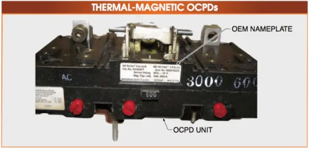
Figure 5. A thermal-magnetic OCPD provides protection against overcurrent and short circuits in MCCBs and is sometimes referred to as a general-purpose trip unit.
An MCCB can only have an OCPD with a continuous current rating of 80% of the frame rating. This is because a thermal-magnetic OCPD has a very broad time-current characteristic curve, which means that OEMs have to make an extra allowance for the circuit breaker to trip without damaging itself from the heat generated by the excess current flow.
MCCB Working/Operating Principle
The operating mechanism of an MCCB opens and closes the contact assemblies and has three positions: open, closed, and trip. Branch circuit breakers of the type used for panelboards and lighting panels are of a fairly simple design. See Figure 6.
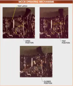
Figure 6. Molded Case Circuit Breaker (MCCB) Operating Mechanism
With the contacts closed, the trip latch is in the latched position (yellow circle). As the contacts are opened and closed, the trip latch position does not move. This type of trip latch is one of the major issues with MCCBs in that it, and other parts of the operating mechanism, is lubricated at the factory.
Current flow through the contacts creates heat, which dries out the lubricant over time. As the factory-applied lubricant dries, it thickens and slows the circuit breaker performance. As it continues to dry, it begins to flake off, and metal-to-metal wear occurs. This metal-to-metal wear and the corrosion that can occur on the trip latch can easily cause the circuit breaker to fail to open as required. The only time the trip latch changes position is when the circuit breaker is tripped.
Note how the trip latch is stationary in the open and closed positions but is different in the trip position. Trip latch malfunction is one of the primary causes of MCCBs failing to operate in accordance with the OEM specifications. Modern large-frame MCCBs often include red mechanical trip buttons. The trip button operates the trip latch directly. The trip latch (yellow arrow in Figure 6) does not move when the circuit breaker is toggled from the open to the closed position. It does move, however, when the circuit breaker is tripped. See Figure 7.
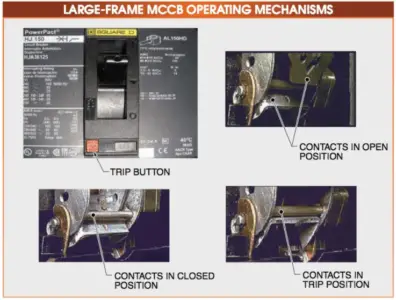
Figure 7. A modern, large-frame MCCB Operating Mechanism labeled diagram
Circuit Breaker Aging and Testing
A study was done by the Nuclear Regulatory Commission (NRC) in NUREG/ CR-5762, Wyle 60101, Comprehensive Aging Assessment of Circuit Breakers and Relays, (written in March 1992) covers the subject of failures in Molded Case Circuit Breakers (MCCBs) that had been in service three to five years with no maintenance.
In this report, various problems were found with the 11 breakers surveyed. Of the 11 circuit breakers, 5 had long-time delay defects and 4 had instantaneous trip problems.
Some circuit breakers had multiple-pole failures and some had both instantaneous and long-time delay problems. Although the survey was limited in number, it is typical of problems seen in the field during testing.
The NRC recommended primary injection testing of the circuit breakers every three years and if they could not be tested, operating the “Push-to-Test” or “Twist-to-Test” mechanism every year. If a circuit breaker does not have such test features, the NRC recommended operating the toggle (handle) several times rapidly twice a year to help maintain functionality.
MCCB Terminal Connections
The safe installation of Molded Case Circuit Breakers (MCCBs) and Insulated-Case Circuit Breaker (ICCBs) depends on proper terminations. If the terminations are not completed properly, they can start fires and damage equipment. Many large ICCBs are either bolted directly to the bus or are of a draw-out construction. See Figure 8. Problems with these types of connections are fairly infrequent.
MCCBs are often connected using stranded-conductor cable or wire, which can cause problems because they have a tendency to loosen over time due to heat cycling. With the terminal connections of standard three-phase thermal-magnetic industrial circuit breakers, the conductors are fitted into the terminal lugs and torqued to specification. The terminal lug can only be used for a specified range of wire sizes and wire types. If the conductor is too small, it will not have the surface area within the lug to carry the expected amount of current.
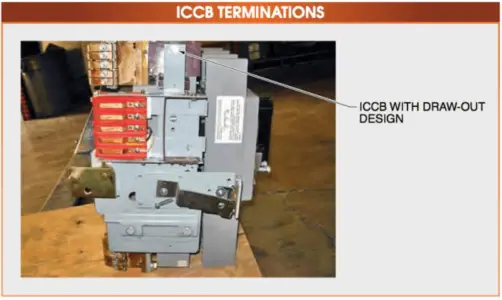
Figure 8. ICCB Termination Diagram
When a small conductor is connected to a terminal lug that should be used for a much larger conductor, there is only point-to-point contact between the conductor and the terminal lug. This type of connection causes overheating at the connection and, if not corrected, will cause the conductor to become annealed. See Figure 9.
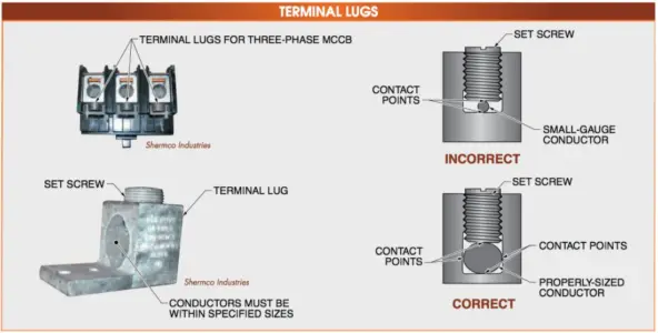
Figure 9. Circuit Breaker Terminal Lugs
When a conductor becomes annealed, it does not carry the proper amount of current due to increased impedance. The increased impedance causes further heating, which then causes the conductor to have a high impedance. Often the insulation around an annealed conductor becomes completely burned off due to the heat being generated. An annealed conductor must be replaced or the annealed portion must be cut off and a new piece of the conductor must be spliced in.
The other issue concerning terminal lugs is improper torquing. If the cable loosens inside the terminal lug, the connection will heat due to increased impedance. This additional heating can also cause the conductor to become annealed. Often when the terminal lug set screw loosens, arcing occurs inside the set screw threads. Typically, this cannot be seen from the outside, so the technician may retighten the set screw and believe the problem is solved. However, the arcing inside the threads typically prevent the set screw from tightening any farther than where the arcing took place. Regardless of how much force is applied to the set screw, it is never completely tightened against the conductor, and overheating continues. See Figure 10.
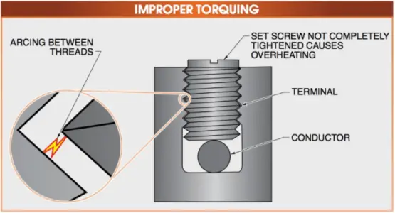
Figure 10. MCCB Improper Torquing