The article discusses various aspects of electric motor protection, focusing on causes of motor failure such as overheating due to electrical or mechanical faults, and outlines protective measures including under-voltage, over-voltage, and environmental protections like enclosures designed for different operating conditions. It also explains the effects of overloads, temperature rise, humidity, and the importance of proper motor cooling and insulation.
One common cause of electric motor failure is temperatures rising above design values. This can occur because of an electrical fault such as single phasing, or be due to mechanical overloading by the driven machine.
The overload might be a relatively small one for a sustained period, or it might be a large and sudden overload such as occurs when a machine locks up because of a mechanical fault.
Short Duration Overload
Standard electric motor design allows for a short duration overload by having a normal running temperature that is well within the capability of the temperature rating of the motor insulation.
When an overload current flows in the electric motor windings, the heat generated by the current is proportional to the square of the current (H ∝ I2). If a motor rated 10 A has an overload of 20 A it will cause (102 = 100, 202 = 400) four times the amount of heat to be generated in the electric motor. This is a serious situation if the overload is sustained for more than a few seconds.
To compound the problem, an overloaded induction motor will slow down with the load and the shaft-mounted fan will supply less cooling air, just when it is most required.
Sustained Overload
If an electric motor has a sustained overload there will be a high temperature rise in the motor and if the temperature becomes higher than the rated temperature of the insulation, the motor will most likely sustain a serious insulation failure.
Locked Rotor
When the rotor of an induction motor is locked (the motor has stalled on an overload), the motor will draw excessive current. The value of the locked rotor current is the same as the DOL starting current and this is usually about seven times the rated current.
The heat generated by a 10 A electric motor with a locked rotor will be approximately 49 times the heat produced at full load (102 = 100, 702 = 4900). At the same time, the shaft-mounted fan is not supplying any cooling air at all. This is a very serious situation and if the correct protection has not been provided, the electric motor can sustain a serious insulation failure.
Under-Voltage Protection
Two kinds of under-voltage protection are available for electric motors controlled by contactors. The first is called no-volt protection because once the voltage is reduced below the holding-in voltage level of the coils the contactors drop out. When power is restored, the motor has to be taken through the starting sequence again until it is up to speed.
The second type is an additional part of a control circuit and keeps the contactors in a holding position for momentary dips in voltage. If the power is restored before the electric motor can coast down appreciably in speed, full power is immediately restored to the motor. One such circuit is illustrated in Figure 2. The control circuit only is shown.
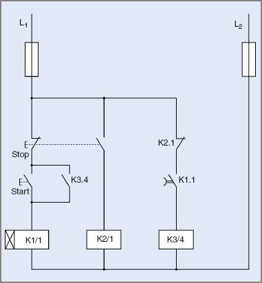
Figure 2 Control circuit diagram for under-voltage protection of electric motor
When the start button is pressed, relay coil K1/l closes immediately. This closes contact K1.1. (As the symbol indicates, the relay can close instantly, but delays on opening.) The circuit is completed for relay K3/4 and it closes and connects the motor through contacts K3.1, K3.2, K3.3 to the three supply lines.
K3.4 contact latches across the start button so holding the circuit in a completed condition. Note the normally closed contact K2.1 is connected in series with K3/4.
To stop the electric motor, pressing the stop button releases relay K1/l and also completes the circuit to relay K2/1 via a mechanically attached switch at the same time. Contact K2.1 opens, releases the main contactor K3/4 and so isolates the motor from the supply.
During a sudden dip in voltage, the delaying action of K1/1 and its accompanying contact K1.1 ensures that the circuit to the main contactor remains complete.
If the power dip is short, the electric motor can restart automatically without an operator being required to initiate a starting sequence. If the power dip is greater than the delay time of the contactor, the starting sequence has to be initiated.
In the interests of safe working, many machines do not lend themselves to this type of circuitry because an automatic restart might be dangerous to the operator.
Over-Voltage Protection
For AC motors connected to a distribution system, over-voltage is a rare occurrence. Over-voltage is more common with long-distance high-voltage transmission lines where lightning strikes are likely to occur. It is a more prevalent problem with variable speed mobile generating plants like those in aeroplanes and automobiles.
As it is undesirable to have an electrical installation operating with a low power factor, consumers are encouraged to keep loads at high power factors. Sometimes, consumers use the uneconomical practice of connecting capacitors in parallel with individual induction motors to correct the power factor.
This can lead to over-voltage transients occurring when an electric motor is switched off. The size of the capacitors should be sufficient only to correct the power factor of each load and preferably ensure that it still has a lagging power factor.
Capacitors connected across an induction motor can cause self-excitation as the motor continues to spin. In some circumstances, this generated voltage can be as high as double line voltage. In normal circumstances, this over-voltage lasts only for a short period and most equipment can cope with the voltage surge.
There are occasions when an electric motor application requires the fitting of surge suppression devices. One example is the submersible bore pump. In its operating location it is a very good Earthing point and, since many bores are fed from overhead lines at a distance from a source of supply, the installation is vulnerable to lightning strikes.
In an attempt to protect the electric motor against what may well be a 500 kV surge over-voltage surge suppressors are fitted. Motor protection is rather uncertain in such circumstances.
Repetitive Starting
The starting current of an induction can be up to seven times the full load current. As shown with the 10 A motor on locked rotor, the heating effect of the current is multiplied by 49 during starting.
The heat generated during a normal start can be handled by the electric motor due the starting current only being present for a brief time. When the motor is up to speed, the shaft-mounted fan will remove any excess heat.
The total heat produced by the current can be determined using Joule’s law.
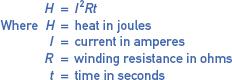
$$H=I^{2}Rt$$
$$\textrm{Where H}=\textrm{heat in joules}$$
$$I=\textrm{current in amperes}$$
$$R=\textrm{winding resistance in ohms}$$
$$t=\textrm{time in seconds}$$
The time for which the high current flows is the important factor here. From the formula, it can be seen that the heat produced is directly proportional to the time in seconds.
In the case of repetitive starts, the amount of heat produced will keep building up due to the extended time factor and the fan not running at full speed long enough the remove the excess heat.
High Ambient Temperature
The temperature rating of an electric motor indicates the maximum temperature that the windings can withstand before permanent damage is done to the windings.
Electric Motors with Class ‘B’ insulation have a maximum operating temperature of 130°C, so that they operate satisfactorily at temperatures up to 130°C.
If the winding temperature exceeds that value some deterioration of the windings will occur. As a general rule of thumb, for every 10°C of temperature rise above the rated value the insulation life is halved.
Temperature Rise
Temperature rise of an electric motor is the difference between the ambient temperature and the motor’s winding temperature. The winding temperature is calculated by the resistance method.
If the ambient temperature is 30°C and the rated maximum temperature of the electric motor is 105°C (Class ‘A’ insulation), then the maximum permitted temperature rise is 65°C.
![]()
$$(105-40=65)$$
However, if the ambient temperature is 40°C, then the maximum permitted temperature rise is only 55°C. The important point here is that the motor may be handling the load when the ambient temperature is low but may suffer over-temperature problems when the ambient temperature is high.
Hot-Spot Allowance
The above calculation assumes that the winding has the same temperature throughout. However, if the temperature has been determined using the resistance method, then the temperature will be the average value.
To offset any hot spots in the winding an allowance is made for safety. A value of 10°C is normally used. So for the above situation with a 40°C ambient, the maximum permitted temperature rise would be 55 − 10 = 45°C.
Example 1
An electric motor has a winding resistance of 16.5 Ω at 25°C. After running at full load for 2 hours, the resistance is measured as 20 Ω. What is the temperature of the windings?
![]()
$$R_{2}=\frac{R_{1}\left [ 234.5+t_{2} \right ]}{234.5+t_{1}}$$
by transposition:
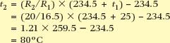
$$t_{2}=(R_{2}/R_{1})\times (234.5+t_{1})-234.5=(20/16.5)\times (234.5+25)-234.5=1.21\times 259.5-234.5=80^{\circ}C$$
Example 2
An electric motor has a winding resistance of 16.5 Ω at an ambient temperature of 25°C. After running at full load for 2 hours, the resistance is measured as 20 Ω. Determine the temperature rise in the windings.
The resistance formula used above can be modified to give:
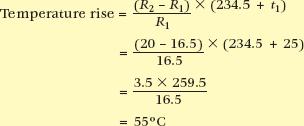
$$\textrm{Temperature rise}=\frac{(R_{2}-R_{1})}{R_{1}}\times (234.5+t_{1})=\frac{(20-16.5)}{16.5}\times (234.5+25)=\frac{3.5\times 259.5}{16.5}=55^{\circ}C$$
An allowance of 10°C is then added to this value to give a value of 65°C. If the maximum permitted temperature of the motor is 105°C, then the motor is operating within its safe temperature range.
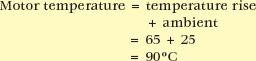
$$\textrm{Motor temperature}=\textrm{temperature rise}+\textrm{ambient}=65+25=90^{\circ}C$$
High Humidity
Electric Motors that are required to operate in areas where the humidity and temperature are high are subjected to moist conditions, which can produce condensation on the inner surfaces of the motors.
In humid areas, where the operating temperature of a machine has a large differential to the off state and ambient, the motor is susceptible to condensation. For example, a machine can sometimes go from 20°C to 40°C, with relative humidity often reaching 100 per cent.
Condensation will occur on a motor surface when the frame temperature of the electric motor is lower than the dew-point temperature of the ambient air.
Any condensation can cause the condition of the windings and inner surfaces to deteriorate over time. This problem is compounded if the motor is installed in an area where there is little or no natural ventilation.
To protect the electric motor and windings against these conditions, motors can be given an extra coating on the windings and on the inner surfaces of the motor. The stator windings are impregnated with a special electrical varnish that is designed to prevent any moisture from reaching the windings. The metal surfaces are also given a special coat of a rust preventative paint.
Environmental Protection
Enclosures
Induction motors are available in many different enclosures, depending on the task allocated to them. Some of the types of enclosures are:
| 1. | Open |
| 2. | Totally enclosed |
| 3. | Duct or force-ventilated |
| 4. | Drip-proof |
| 5. | Flameproof |
| 6. | Weatherproof |
| 7. | Submersible |
| 8. | Explosion-proof. |
AS/NZS 13521 lists more than a dozen methods for cooling induction motors. Adding to this a variety of different mounting types, such as horizontal or vertical, tends to make the list rather large.
The type of electric motor enclosure chosen depends on the conditions under which it has to function. The enclosures listed below are general main groups but under each, there can be many subgroups.
Open Motors
The ends of the machine are open, allowing free ventilation through and around the windings. Air is circulated through the motor by a fan attached to the motor shaft. The electric motor needs to be installed in a clean and dry atmosphere.
Protected Motors
With the protected electric motor enclosure, the windings and live parts are protected mechanically but a free flow of air is still drawn through the motor by a fan attached to the motor shaft. The protection is often obtained by fastening wire mesh or perforated metal over enclosure openings.
Drip-Proof Motors
Drip proofing is an advance on the protected type of enclosure. The openings are further protected by a hood, preventing foreign materials and moisture falling vertically onto the motor and entering the motor. The hood may be incorporated into the enclosure during manufacture of the electric motor.
Duct or Force Ventilated
With forced ventilation, a fan forces air through the electric motor at a constant rate. This is essential where the motor is connected to a variable speed drive and is required to run at reduced speed with a load. In these conditions the electric motors own fan will not be spinning fast enough to deliver the required amount of cooling. A motor with forced ventilation is shown in Figure 3.
Where installed, the electric motor might not be in an atmosphere of suitable composition to allow clean air to flow through the motor. Corrosive atmospheres, high temperatures, high humidity and similar conditions are examples. For ventilation, cool and clean air must be drawn in from outside the installation.
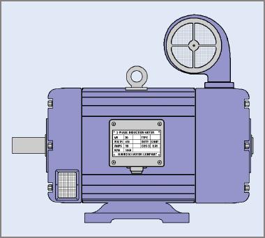
Figure 3 A three-phase electric motor with fan-forced cooling
There are two major types of ventilation in this case. In one type, air is drawn from outside through a duct and can be expelled inside the installation, or it may have to be ducted to the outside atmosphere again. In the second type, a blower is installed outside and air is forced through a duct to the motor. It may be expelled directly, or it can be ducted outside into the atmosphere again. It is a method of cooling usually adopted for very large electric motors.
Totally Enclosed
In the totally enclosed type (see Figure 4) there is no contact between the air inside the machine and the air outside. The fan attached to the shaft is external to the motor proper and enclosed within its own housing.
The electric motor housing is usually ribbed, and the air driven by the fan flows along the ribs and removes the internal heat by conduction through the housing.
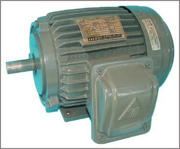
Figure 4 Totally enclosed fan-cooled electric motor
The heat is removed from the electric motor at a slower rate than by direct cooling but the increased surface area created by the finning process assists. Modifications to this method of enclosing a motor enable it to be classified as waterproof, weatherproof or submersible.
Flameproof
The flameproof type (see Figure 5) is a totally enclosed electric motor with additional precautions to seal the bearings and assembly contact surfaces. Electrical connections are made through a special sealed gland. The electric motor housing is made strong enough to withstand any internal explosion and still prevent sparks escaping to the external atmosphere.
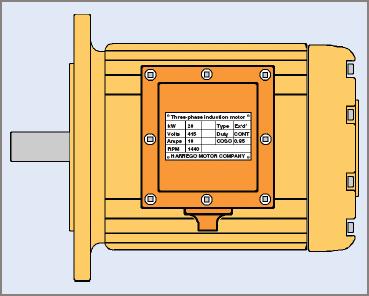
Figure 5 Typical flange-mounted flameproof electric motor
The electric motor is used when there are flammable gases and the risk of explosion if sparks enter this atmosphere. The enclosure must comply with stringent regulations before being classified as flameproof.
Electric Motor Protection Key Takeaways
The various protective measures and design considerations discussed are crucial for ensuring the reliable and safe operation of electric motors across different applications. Overheating due to electrical faults, mechanical overloads, or environmental factors like humidity can cause significant motor damage and downtime if not properly managed. Protective features such as under-voltage and over-voltage protections, suitable enclosures, and effective cooling methods help prevent failures, extending motor lifespan and reducing maintenance costs. Understanding the impact of load conditions, temperature rise, and environmental stresses allows for the correct specification of motors and their protective systems, which is essential in industrial, commercial, and specialized applications such as submersible pumps or explosion-proof environments.