Simple RC and RL circuits can be used as low pass and high pass filters. In this article, we will look at RC and RL low pass filters along with their cutoff frequencies.
RC Low Pass Filters
An RC circuit acts as a low pass filter when constructed as shown in Figure 1. In the circuit shown, the resistor is positioned directly in the signal path, that is, directly between the source (E) and the load. The capacitor is connected from the signal path to ground, in parallel with the load. Therefore, VRL = VC (as shown in the figure). When a capacitor (or another component) is connected from a signal path to ground, it is referred to as a shunt component.
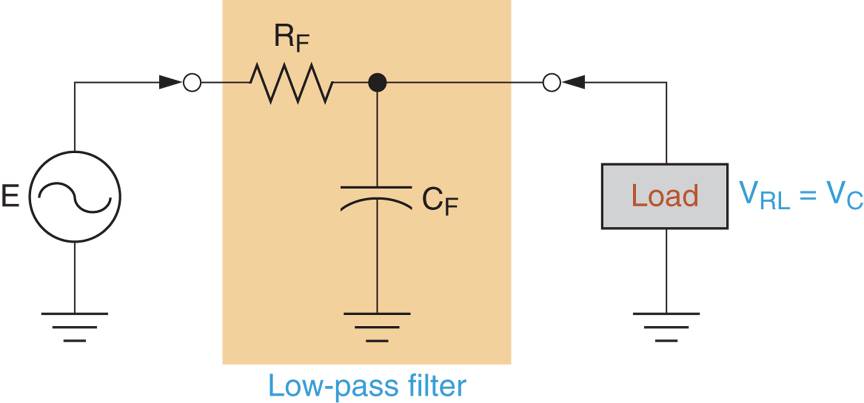
Figure 1: An RC Low-Pass Filter Circuit Diagram
The filtering action of the circuit in Figure 1 is a result of the capacitors response to an increase in frequency. This response can be explained using the curve and circuits in Figure 2.
The curve in Figure 2a shows the relationship between capacitive reactance (XC) and operating frequency (f). As the curve indicates, a capacitor has near infinite reactance when its operating frequency is 0Hz. With this in mind, look at the circuit shown in Figure 2b. Assuming that the input frequency is 0Hz, the capacitor effectively acts as an open circuit, so it is left out of the equivalent circuit. In this case, the voltage across the load equals the difference between E and VRF.
At the opposite end of the reactance curve, the value of XC approaches 0Ω. When this is the case, the filter has the equivalent circuit shown in Figure 2c. As you can see, the capacitor is represented as a short circuit in parallel with the load. In this case, VL = 0V.
Between the extremes shown in Figure 2 lies a range of frequencies over which VRL decreases, so does the circuit output power. As a result, the circuit has a frequency response curve.
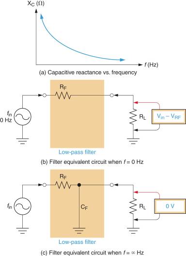
Figure 2: RC Low-pass Filter Operation and Frequency Response
Upper Cutoff Frequency (fC)
The upper cutoff frequency for an RC low pass filter is determined by the circuit resistor and capacitor values. By Formula,
\[\begin{matrix}{{f}_{C}}=\frac{1}{2\pi RC} & {} & \left( 1 \right) \\\end{matrix}\]
Where
fC = the circuit cutoff frequency
R= the total circuit resistance
C= the value of the filter capacitor
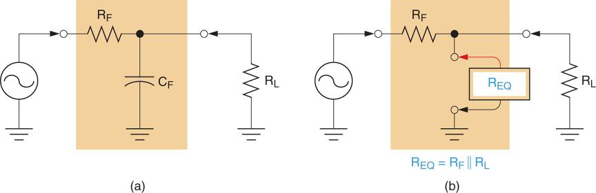
Figure 3: Resistance in RC Low-Pass Filter
The value of R used in the equation is the total resistance as seen by the capacitor. The total resistance (as seen by the capacitor) in Figure 3a can be measured by connecting an ohmmeter across the open capacitor terminals as shown in Figure 3b. The total resistance seen by the capacitor (REQ) has a value of:
\[\begin{matrix}{{R}_{EQ}}={{R}_{F}}||{{R}_{L}} & {} & \left( 2 \right) \\\end{matrix}\]
and
\[\begin{matrix}{{f}_{C}}=\frac{1}{2\pi {{R}_{EQ}}C} & {} & \left( 3 \right) \\\end{matrix}\]
Remember that || symbol in equation 2 indicates that the values are solved as parallel resistors. You can use either the reciprocal approach or the product over sum approach to solving for the value of REQ. Example 1 demonstrates the procedure for calculating the cutoff frequency of an RC low-pass filter.
Example 1
Determine the cutoff frequency for the circuit shown in figure 3a.
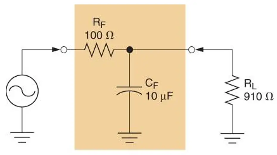
Figure 3a: RC Low-Pass Filter Example
Solution
First, the circuit resistance (as seen by the capacitor) is found as:
\[{{R}_{EQ}}={{R}_{F}}||{{R}_{L}}=\frac{100\times 910}{100+910}=90.1\Omega \]
Now, the cutoff frequency of the circuit can be found as:
\[{{f}_{C}}=\frac{1}{2\pi {{R}_{EQ}}C}=\frac{1}{2\pi \times 90.1\Omega \times 10\mu F}=177Hz\]
This result indicates that the power gain of the circuit is reduced to 50 % of its maximum value when the operating frequency reaches 177 Hz. The frequency response curve for the circuit is shown in Figure 3b.
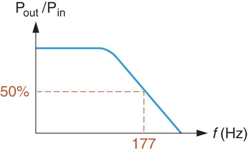
Figure 3b: Frequency Response Curve of RC Low-Pass Filter
RL Low Pass Filters
An RL circuit acts as a low pass filter when constructed as shown in Figure 4. In the circuit shown, the inductor is the series component and the resistor is the shunt component.
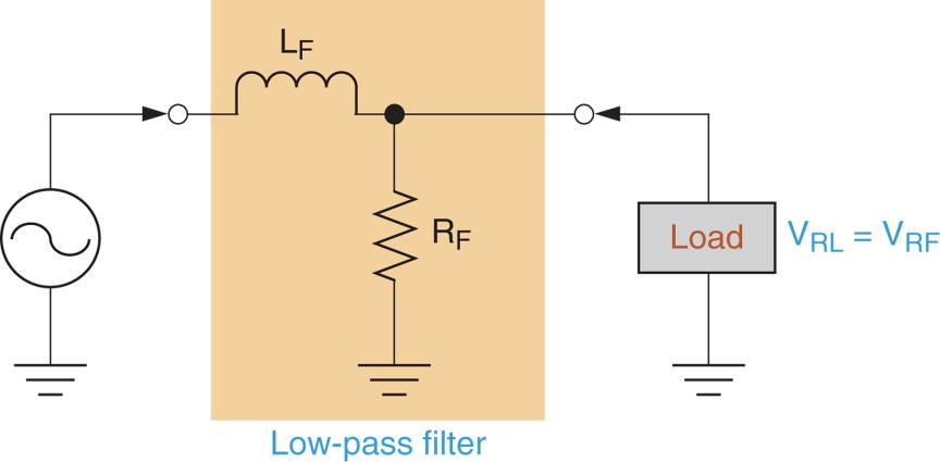
Figure 4: An RL Low-Pass Filter Circuit Diagram
The filtering action of the circuit in Figure 4 is a result of the inductors response to an increase in operating frequency. This response can be explained using the curve and equivalent circuits in Figure 5.
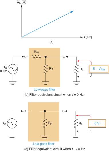
Figure 5: RL Low-Pass Filter Operation and Frequency Response
The curve in Figure 5a shows the relationship between inductive reactance (XL) and operating frequencies (f). As the curve indicates, the reactance of an inductor is 0Ω when the input frequency is 0Hz. With this in mind, look at the equivalent circuit shown in Figure 5b. Assuming that the input frequency is 0Hz, the inductive reactance is 0Ω. However, the inductor does have some amount of winding resistance (RW). Therefore, a resistor representing the winding resistance of the coil has been included in the equivalent circuit. In this case, the load voltage equals the difference between the source voltage (E) and the voltage across RW.
As shown in the reactance curve, increases in operating frequency cause proportional increases in the value of XL. Theoretically, the operating frequency can become high enough for the inductor to effectively act as an open. When this is the case, the filter has the equivalent circuit shown in Figure 5c. As shown in the circuit, the inductor is represented as a break in the conductor (because of its near-infinite reactance). In this case, VRL = 0V. Between the extremes represented in Figure 5, lies a range of frequencies over which VRL decreases from E – VRW to 0V.
Upper Cutoff Frequency (fC)
The upper cutoff frequency for an RL low pass filter is determined by the inductor and the parallel combination of RF and RL. By Formula,
\[\begin{matrix}{{f}_{C}}=\frac{{{R}_{EQ}}}{2\pi L} & {} & \left( 4 \right) \\\end{matrix}\]
Where
REQ=RF||RL
Example 2 demonstrates the calculation of fC for an RL Low-Pass Filter.
Example 2
Calculate the cutoff frequency for the circuit shown in figure 6.
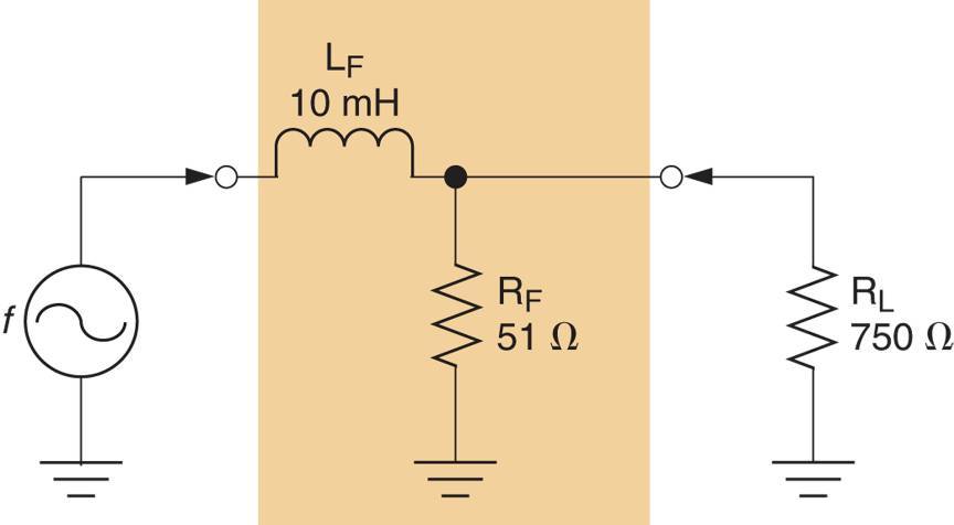
Figure 6: RL Low-Pass Filter Example
Solution
First, the value of REQ is found as:
\[{{R}_{EQ}}={{R}_{F}}||{{R}_{L}}=\frac{51\times 750}{51+750}=47.8\Omega \]
Now, the cutoff frequency of the circuit can be found as:
\[{{f}_{C}}=\frac{{{R}_{EQ}}}{2\pi L}=\frac{47.8\Omega }{2\pi \times 10mH}=761Hz\]
This result indicates that the power gain of the circuit is reduced to 50 % of its maximum value when the operating frequency reaches 761 Hz. The frequency response curve for the circuit is shown in Figure 7.
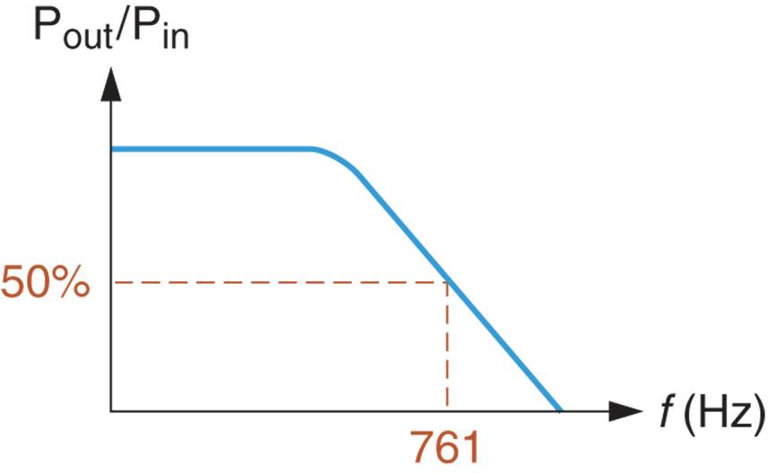
Figure 7: Frequency Response Curve of RL Low-Pass Filter
A Look Ahead
We have now discussed the operation and analysis of RC and RL low pass filters. In the following section, we will take a similar look at RC and RL high pass filters. As you will see, most of the principles discussed in this section apply to those circuits as well.