Safety in relation to programmable controllers (PLC) needs to be looked at from three angles: PLC safety and protection, equipment safety and safety of personnel.
Programmable Controller (PLC) Safety and Protection
PLCs in an industrial environment require a certain amount of mechanical protection as well as basic electrical protection. The transducer connections radiate out from the controller and are subject to spurious voltages being induced in the connecting cables. This is generally referred to as ‘electrical noise’ and can be misinterpreted by the microprocessor as a form of input. It can produce erratic equipment operation and incorrect data entry—and can prove difficult to trace as the source of trouble.
In the industrial context, there are usually many machines and other equipment being switched on and off continually. This causes voltage spikes and surges in the main supply. Since a PLC typically operates at extra-low voltage, a transformer is employed to reduce the mains voltage to a suitable value, and consequently these surges in voltages are transferred through the transformer to the processor.
Suppression of this electrical noise becomes an essential requirement for satisfactory operation of a PLC. This might mean applying special runs with shielded wiring to the transducers as well as noise suppression at the transducer.
PLC input-output modules use photocouplers, also known as ‘opto-isolators’ or ‘optocouplers’. The main function of an opto-isolator is to block high voltages, voltage surges and transients. These are designed to prevent the system and other sensitive parts from damage and disruption of the PLC operation. Phototransistor optocouplers can be used for input and output modules, while photo-SCR (silicon-controlled rectifier) and photo-TRIAC types are generally used for output modules.
Controlled Equipment Safety
A PLC cannot be relied upon and used as the only control for the safety-related parts of the machine. Safety switches, safeguarding and emergency stops are incorporated into the equipment and circuit design.
Where machinery is controlled by a PLC, precautions have to be taken to ensure that erratic operation by a PLC does not lead to the destruction of that machinery. This usually means that extra equipment has to be installed. For example, a second limit switch might have to be installed as a back-up to one that is actually controlled by the PLC. In the case of heating baths, a second temperature sensor might have to be installed as a back-up to the main one that sends information to the processor and overrides any function of the PLC.
Safety relays can be installed for the monitoring and control of door safety switches, guards and emergency stop switches. They are installed to provide additional control equipment safety by detecting circuit fault conditions including:
- wire breaks
- faulty contactors
- faulty safety actuators
- timing faults.
Figure 1 illustrates the concept of safety relays; door safety and emergency stop as an equipment safety system separate to—and not solely relying on—PLC control. You can see that the emergency stop pushbutton has two sets of contacts. The normally open contacts are connected as the PLC Input 3, more for monitoring than stop control. If the PLC hardware fails or the logic program software does not respond to this input, there is also a hard-wired fail-safe redundancy measure. Figure 1 shows that when the safety relay operates, all power is removed from the PLC output module and actuators.
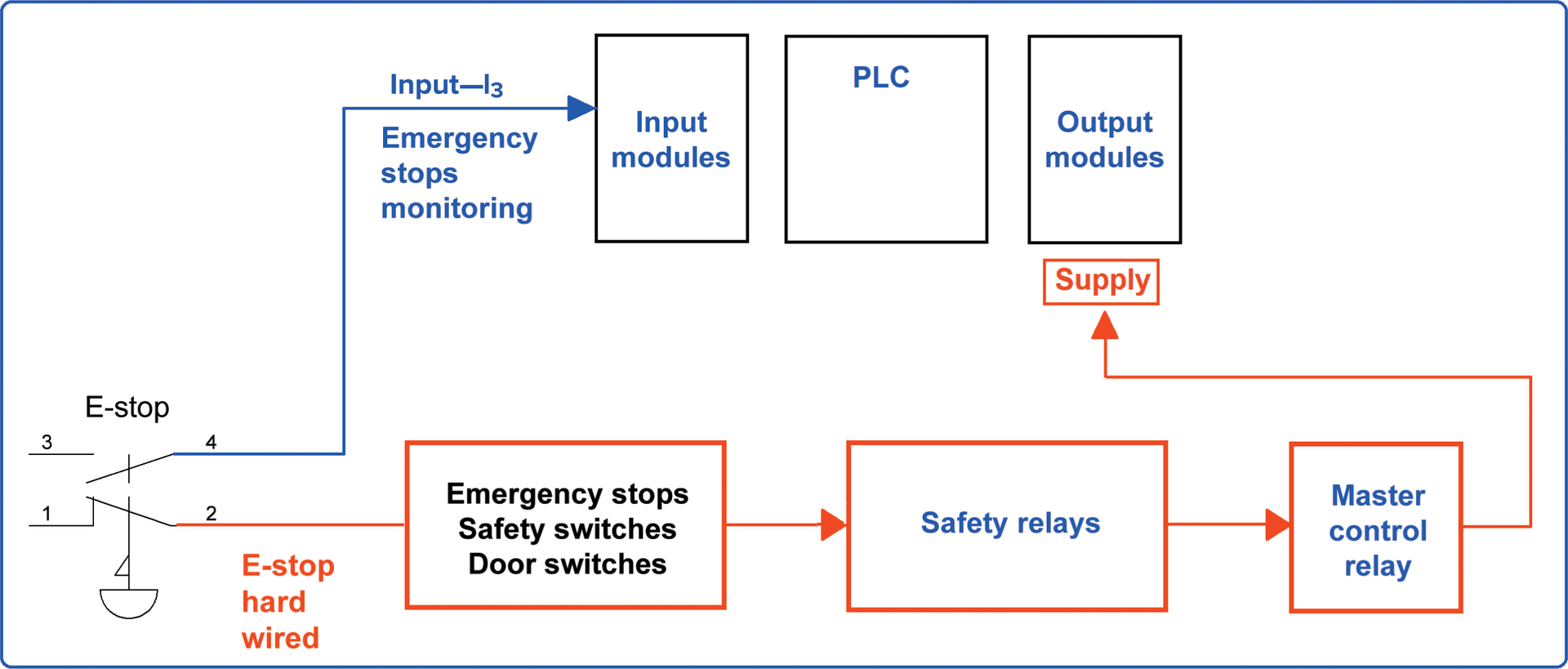
Figure 1. Block diagram of PLC stop control.
The door safety switches, emergency stop loop and other safeguarding measures are series connected with one or more safety relay circuits. These relays are wired to safely and appropriately isolate power, including PLC output module actuators.
Safeguarding prevents a person from coming into contact with hazards, or even aims to eliminate hazards before that becomes a risk. Examples of equipment safeguarding include:
- equipment and machinery guards—fixed, movable and powered guards
- light curtains—presence detection for hands, arms, head and upper body
- safety mats—(pressure-sensitive mats) ensuring safe positioning of workers operating equipment and preventing them from leaning into a machine process or operation
- two-hand control—for example, the safe operation of guillotines for the prevention of hand, arm and body parts against amputation and crush injuries.
Two-hand control is having two separate, hand-operated switches connected in series with a stop control circuit. These are commonly combined with light curtains, guard covers and operator pressure-sensitive mats to ensure no part of the body can be caught, cut, crushed or severed. Equipment design allows for a number of different machine stop situations. These include:
- Category 0—an uncontrolled stop, equivalent to pulling the plug; immediate removal of power to the machine actuators.
- Category 1—a controlled stop, equivalent to a graceful stop then pulling the plug; a controlled stop with power available to the machine actuators to achieve the stop and then removal of power.
- Category 2—a controlled stop with power still available to the machine actuators.
Safety of Personnel
Operators or maintenance personnel must be protected against any erratic behaviour of the controlled process or task. Unexpected starting or stopping of equipment due to spurious signals getting into the system wiring can cause accidents. An emergency stop button should be included as part of the installation to override all other input signals.
Properly designed emergency stop systems ensure that operating the emergency stop button while the machine is in mid-cycle should result in equipment and machinery coming to a stop quickly and safely. Operation of the emergency stop will also prevent machine start-up. This would in most situations be equivalent to a Category 0 stop condition.
Emergency stops need to be hard wired to cut power to PLC outputs through safety relay or master control relay circuits as a fail-safe safety measure. E-stops may have additional contacts used as PLC inputs for monitoring, indication and control circuit function, as can be seen in Figure 1.
What are the three key requirements of the operation of a programmable controller?
- status of inputs
- program
- tatus
Explain the purpose of emergency stop systems.
Emergency stop systems ensure that operating the emergency stop button results in equipment and machinery coming to a stop quickly and safely without causing harm or damage. Operation of the emergency stop will also prevent machine start-up.
Explain what safety relays are.
Safety relays are installed for monitoring and control of door safety switches, guards and emergency stop switches. They are installed to provide additional control equipment safety to detect circuit fault conditions.
PLC Safety and Protection Key Takeaways
The importance of safety in programmable logic controllers (PLCs) cannot be overstated, especially given their widespread application in industrial automation. Ensuring PLC safety and protection shields critical systems from electrical noise and voltage surges, preserving functionality and preventing system failure. Meanwhile, equipment safety ensures that controlled machinery operates within safe boundaries, even in the event of PLC malfunction, through redundant systems like safety relays and backup sensors. Lastly, the safety of personnel is paramount, as unexpected machine behavior can lead to serious injury. Emergency stop systems and safeguarding measures like light curtains, safety mats, and two-hand controls create multiple layers of defense against accidents.