This article covers Triac Construction, Operating Principle, Circuit Characteristics, Testing Procedure, and Applications, along with the relevant circuit and block diagrams.
In many situations, control of AC power is required. Both the SCR and the GTO thyristor conduct current in only one direction. They are, therefore, not suited to controlling AC power when used alone.
To control AC power, two SCRs may be used in an inverse parallel connection, as shown in Figure 1.
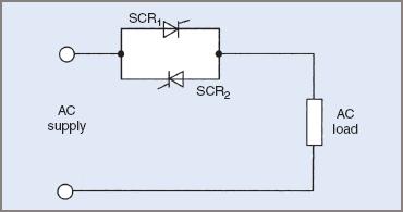
Figure 1 Control of AC power with inverse-parallel SCRs Diagram
With this circuit arrangement, each SCR conducts in alternate half-cycles of the supply. While this arrangement is popular for high-current applications, the two SCRs can be replaced by a single device called a triac. Triacs are available with current ratings up to about 150 A.
What are TRIACs in Power Electronics?
The triac is a three-terminal bi-directional thyristor. It was developed as a device to control AC power. The triac replaces a pair of inverse parallel-connected SCRs. For low-to medium-current applications (up to about 100 A), the triacs is less costly than two SCRs. For currents above 100 A, two inverse parallel-connected SCRs might prove to be more economical than a single triac.
A triac operates in the same manner as an SCR but has the added ability to conduct in both directions. The layer construction of a triacs is quite complex. A simplified representation, together with the standard symbol, is shown in Figure 2.
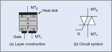
Figure 2 Triac layer construction and circuit symbol and Diagram
The terminals of the triac are referred to as main terminal 1 (MT1) and main terminal 2 (MT2), owing to the fact that it is a bi-directional device and, therefore, really does not have an anode and a cathode. The gate terminal is the control terminal, as is the case with the SCR.
TRIAC Principle of Operation and How They Work
A triac operates in the same manner as an SCR but conducts in both directions. Triac operation may be summarized as follows:
- Conduction is blocked until the forward or reverse blocking voltage is exceeded.
- Conduction may be initiated by a gate-trigger pulse, with either MT1 or MT2 positive, and with either positive or negative gate pulses.
- If MT current exceeds the latching current, the triacs will remain on (latched on) when the gate pulse is removed.
- If MT current falls below the holding current, the triac will turn off.
- The voltage drop across a conducting triac is relatively constant and is approximately 1.0 to 2.0 V.
Like the SCR, the latching and holding currents are very small values, the latching current being slightly greater than the holding current. Typical values for a 400 V 8.0 A triac are:
- holding current—8.0 mA
- latching current—10.0 mA.
TRIAC Four Triggering Modes of Operation
Given that the triac can conduct in both directions, it is possible to establish four methods or modes of triggering. These modes relate to the polarity of terminals MT2 and the gate with respect to MT1. The four modes are specified in Table 1.
Table 1 TRIAC Four Triggering Modes of Operation
| Polarity (with respect to MT1) | ||
| Triggering mode | MT2 | Gate |
| Mode 1 | Positive | Positive |
| Mode 2 | Negative | Negative |
| Mode 3 | Positive | Negative |
| Mode 4 | Negative | Positive |
The four triggering modes are represented in Figure 3.
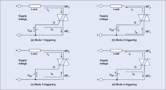
Figure 3 Triac triggering modes circuit diagrams
The triggering sensitivity of a triac (the value of gate current needed to turn the triac on) is best in modes 1 and 2. Mode 3 is sometimes slightly less sensitive than 1 and 2, while mode 4 is the least sensitive and is not usually recommended.
When gate-trigger pulses of both positive and negative polarity are available, a triac will be triggered in modes 1 and 2. In situations where trigger pulses of one polarity only are available, the gate is made negative with respect to MT1, so that the triac is triggered in modes 2 and 3.
TRIAC Characteristics Curve and Ratings
The forward and reverse characteristics of a triac are shown in Figure 4. It should be noted that the characteristics are the same in both directions, unlike a p–n diode or an SCR.
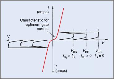
Figure 4 Triac characteristics curves
Like the SCR, the triac has a number of electrical ratings, the most significant being:
1. Blocking voltage (VDRM)—the maximum voltage that the triac can block in either direction when the gate current is zero
2. Maximum on-state current (IT(RMS))—the maximum continuous RMS value of current that the triac can safely carry. It may be necessary to mount the triac on a heat sink to dissipate the heat developed in the device at this value of current.
3. Maximum peak one-cycle non-repetitive current (ITSM)—maximum peak value of current that the triac can safely carry for only one cycle of the supply. This value is usually much greater than the maximum on-state current.
4. Maximum rate of rise of current (di/dt)—the maximum rate of rise of MT current when the triac is switched from the off to the on state. If the current rises too quickly, the current density in the silicon wafer might be high enough to damage the device.
5. Holding current (IH)—the minimum current that will support conduction. If the current falls below this value, the triacs will relax back to the off-state.
6. Latching current (IL)—the minimum current required to latch the triac into the on state. If the current does not rise above this level, the triacs will turn back off when the gate current is removed.
7. Rate of rise of off-state voltage (dv/dt)—the maximum rate of rise of off-state voltage, in either direction. If the off-state voltage rises at a faster rate than this value, the triacs may switch back to the on-state.
8. On-state voltage drop (VTM)—the maximum expected voltage drop measured across the triacs in the on-state.
How to Protect TRIACs?
A triac requires protection against the same occurrences as an SCR. In summary, they are:
- Short-circuits—protection is provided by special HRC fuses.
- Rapidly rising currents—series inductors may be used to limit the rate of rise of current (di/dt).
- Rapidly rising off-state voltages—a snubber network is connected in parallel with the triacs to limit the rate of rise of off-state voltage (dv/dt).
- Excessive junction temperature—triacs are usually mounted on a heat sink to limit junction temperature. Manufacturers’ data usually provides information on the required heat sink type.
The circuit in Figure 5 overleaf shows how electrical protection may be applied to a triac.
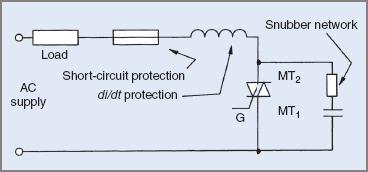
Figure 5 Triac protection circuit diagram
In some lower-power applications, the special HRC fuse and the series inductor may be omitted. This is due to the high cost of these components when compared with the cost of the triac.
How to Test TRIACs
A number of ‘in circuit’ tests can be carried out on a triac in a similar fashion to those for the SCR. A simple test using an analog ohmmeter may be used. This is similar to a test of an SCR using an ohmmeter. Table 2 outlines the expected results from this test.
Table 2 TRIAC Test Results—Serviceable Triac
| Test polarity | ||
| Positive (+) | Negative (−) | Expected resistance |
| (a) MT2 | MT1 | High (infinite) |
| (b) MT1 | MT2 | High (infinite) |
| (c) MT2 | MT1 & gate | High (infinite) |
| (d) MT1 & gate | MT2 | High (infinite) |
| (e) MT2 & gate | MT1 | Low (20 Ω) |
| (f) MT1 | MT2 & gate | Low (20 Ω) |
If, from these results, the triacs appears to be serviceable, it may be further tested to determine if it can be triggered and latched on in a similar manner to the SRC. However, some caution needs to be exercised in this test. High current triacs might not be able to be triggered by the current available from an ohmmeter. The tests are shown in Figure 6.
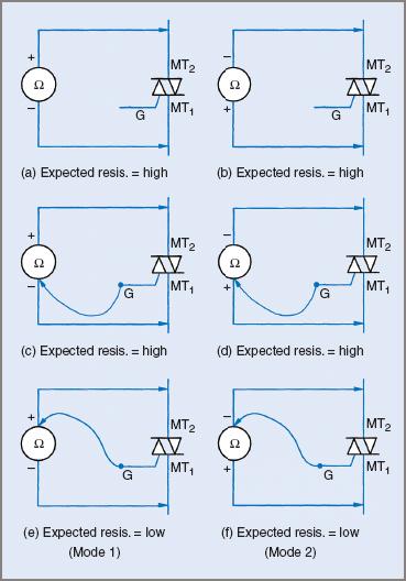
Figure 6 Triac testing modes circuit diagrams
If the multimeter used cannot deliver sufficient current to cause a triacs to trigger on and latch, it may be necessary to conduct more extensive and complex testing to determine the condition of the triac.
What are the Main TRIAC Applications?
Triacs are used extensively in low- to medium-power applications. For higher AC power and variable frequency control of AC motors, SCRs are preferred. Typical applications are:
- Illumination Control (Lamp Dimmers)
- Fan Speed Control (Ceiling Fans)
- Heating Loads
- Welding Equipment
- Motor Speed Control (With Limitations)
- Ac Electromagnets
- Solid State Relays (Replaces A Contactor).
TRIAC Key Takeaways
Understanding the construction, operation, characteristics, testing, and protection of triacs is essential due to their widespread use in controlling AC power in modern electronic systems. Unlike SCRs, triacs offer bidirectional current conduction, making them highly suitable for single-device AC switching. This reduces component count and cost in many low- to medium-power applications. Their ability to control devices such as dimmers, fans, heaters, and even motor speeds demonstrates their versatility.