The article explains different methods of motor control, including Two-Wire Control, Local or Remote Operation, Combined Stop-Start and Automatic Control, Jog Control, and Reversing Circuits. It also introduces Ladder Diagrams and NEMA Standards used for representing control circuits in various formats.
Two Wire Control
The stop and start push-button switches, in motor and other control circuits, are convenient ways to operate circuits. It is easier to press a button rather than operate a toggle or turn a handle.
To provide extra start positions, all that is needed is to connect extra start push-buttons in parallel with the first. To stop or de-energize the circuit extra stop push-button switches are placed in series with the first.
In Figure 1 there are two start and two stop push-button switches. As is usual, the start push-buttons are normally open and the stop push-buttons are normally closed. They have been labelled ‘start 1’, ‘start 2’, ‘stop 1’ and ‘stop 2’ for clarity.
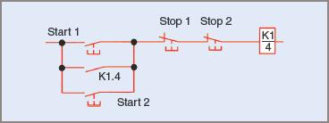
Figure 1 Two start and stop control positions in a circuit
A variation on the control circuit in Figure 1 is the provision of only one start position with multiple stop positions. This can arise when a number of emergency stop positions might be required in a plant.
Only one push-button switch will start the operation but if there is a malfunction in the plant it can be stopped by operators at any number of positions. It requires that all the stop push-button switches are connected in series (see Figure 2).
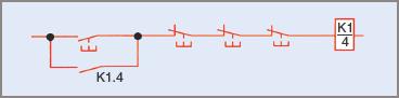
Figure 2 Multiple stop control positions
Local or Remote Operation
In some operations it may be necessary to shift the operating position of the stop–start push-button switches. To avoid the possibility of someone operating the machine at the incorrect position, the circuit of Figure 2 is amended so that only one position at a time can be used. This is often referred to as ‘local’ or ‘remote operation’. Figure 3 is a circuit representation of this type. On the left side of the diagram is a hand-operated changeover switch, which switches into circuit either the upper local or lower remote push-button switches. This type of circuit requires an extra contactor contact and only a simple changeover switch.
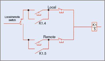
Figure 3 Remote or local operation control
Two-Wire Control
Many motor control circuits use an automatic start control. This could be, for example, from a thermostat on a refrigerator, a float switch on a water tank or a pressure switch on an air compressor. Because there is no other stop–start control and only two wires need to be run to the actuating device, is it usually referred to as ‘two-wire control’.
Figure 4 is a simple two-wire control circuit. In this case the controlling device is a pressure switch, which is represented by the lower case p in the square.
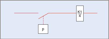
Figure 4 Two-wire control by a pressure switch
Two-Wire and Push-Button Control
In some cases it might be necessary to start a motor-controlled device using a push-button switch but allow another control to turn it off. This type of circuit is shown in Figure 5. It has normal stop–start control with a float switch connected in series with the stop push-button. This would enable a pump to be started and then switch off automatically when a tank is full.
The motor could be stopped at any time while running but it could not be restarted after an automatic stop until the water level fell and the float switch closed again.
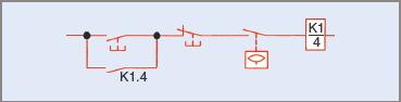
Figure 5 Combined stop-start and automatic control
Start Stop Jog Control
When a push-button switch is connected so that a circuit operates only while the switch is held depressed it is called ‘jogging control’. It is sometimes necessary to ‘jog’ a machine to a certain position, so that adjustments may be made. It would be possible to juggle both start and stop push-buttons using two hands, but it is not good practice or reliable and could be dangerous. It is more efficient to install a special push-button for this function.
In the schematic circuit diagram in Figure 6 the jogging push-button switch is a push button changeover switch with a normally closed and a normally open position.
In its normal position the circuit operates as a simple stop/start control. When the jogging button is pressed, the hold-in contact, K1.4, is isolated and the start push-button switch is bypassed. While the jogging button is pressed, coil K1.4 is energized.
When the button is released, the circuit to the coil is opened and then remakes the normally closed contact so that normal operation is possible. The jogging push-button sometimes includes a small delay on reclosing to give the contactor time to open contact K1.4.
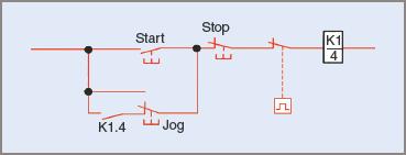
Figure 6 Jogging push-button switch in a control circuit
Reversing Circuits
To reverse a three-phase motor, all that is necessary is to interchange two supply lines to the motor. This can be accomplished by using two contactors, as in the schematic circuit diagram in Figure 7.
When either K1.1, K1.2 and K1.3, or K2.1, K2.2 and K2.3 contacts close, the motor will operate either in a forward direction or in the reverse. Examination of the power circuit will show that two supply lines would be short-circuited if both contactors closed at the same time.
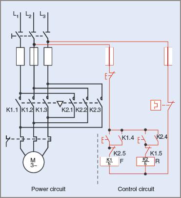
Figure 7 Schematic circuit diagram of a reversing contactor
This can be prevented in two ways. The small equilateral triangle and the broken lines between the two sets of power contacts signify that the two contactors are ‘mechanically interlocked’. This means that if one contactor is closed it is mechanically impossible for the other to close.
The second method is to use ‘electrical interlocks’ in each contactor coil circuit. This can be seen in Figure 7, where the normally closed contact K2.5 is in the forward coil circuit and the normally closed contact K1.5 is in the reverse coil circuit. This means that when contactor coil K1/5 is energized, contact K1.5 will open. Then, if the reverse push-button switch is pressed, coil K2/5 cannot be energized. The same applies to the reverse operation.
Only one stop push-button is used and the thermal overload contact is also in series with the stop button. By necessity, the stop push-button switch is ahead of the forward and reverse push-buttons so that it can control both.
Ladder Diagrams
Control circuits in particular can be drawn as ‘ladder’ diagrams. They are called that because the supply lines are drawn on each side and the circuit component parts are drawn across them so the result is that it looks like the stiles of a ladder.
Ladder diagrams also follow the requirement that energy flow and sequence of events be from left to right and top to bottom whenever possible in a similar manner to common drawing practice in this country.
These diagrams are a step towards programming logic controllers and are mostly used with programming in mind. The control circuit of Figure 7 has been redrawn in a horizontal orientation and is shown in Figure 8. Symbols as recommended in AS/NZS 1102 are used. The circuit, however, is identical to that of the control circuit in Figure 7.
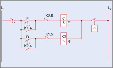
Figure 8 Control circuit of Figure 7 drawn with a horizontal layout
In other countries different standard symbols are often used. In the USA more than one set of standards is used, but one popular one is called the NEMA standard. The name is short for the National Electrical Manufacturers Association.
The control circuit of Figure 8 redrawn to NEMA standards is shown in Figure 9. It is still the identical circuit except that now each overload is shown separately as three normally closed contacts.
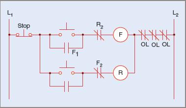
Figure 9 Reversing control circuit drawn to NEMA standards
Many of the programmable logic controllers in this country and others use this standard and the programmers are oriented towards this standard. Circuit diagrams supplied with the controllers are, more often than not, drawn to NEMA standards.
Two Wire Control Key Takeaways
Understanding the various methods of motor control—such as Two-Wire Control, Local or Remote Operation, Combined Stop-Start and Automatic Control, Jog Control, and Reversing Circuits—is essential for designing efficient and safe electrical systems in industrial and commercial settings. These methods enhance operational flexibility, improve safety through emergency stop integration, and allow for automation using sensors and external switches. Moreover, representing these circuits using Ladder Diagrams and adhering to standards like NEMA ensures clarity, compatibility, and easier troubleshooting. In practical applications, these control systems are widely used in machinery, HVAC systems, water treatment plants, and manufacturing units, making them crucial for modern automation and control engineering.