The article provides an overview of contactors and relays, focusing on their construction, operation, and schematic representation in electrical circuits. It also explains the types of contacts, timing functions, and various methods of symbolically representing contactors in circuit diagrams.
A relay is simply an electromagnetically operated switch. A contactor is also an electromagnetically operated switch that controls power to a load. A contactor actually is just a large relay and it is sometimes difficult to say whether a device should be called a relay or contactor in any given circuit application.
In effect, the two terms are the same. In this section the term contactor is generally used but reference could also be made to relay contacts and power contacts, all operated from the same device.
Construction and Operation of Contactors
A contactor consists of three basic parts: the operating coil, the associated magnetic circuit and the contacts that are actuated by the coil.
Figure 1 is a representation of a very old type of contactor. It clearly shows the coil, the operating part of the magnetic circuit and a single contact.
Modern contactors look like that shown in Figure 2, but the principle of operation is exactly the same as the representation in Figure 1.
- When the coil is energized a magnetic field is produced in the magnetic circuit. This attracts the hinged armature, against the tension of the spring, to complete the magnetic circuit.
- The movable contact attached to, but insulated from, the armature closes against the fixed contact.
- When the coil is de-energized the armature springs open and also opens the contact.
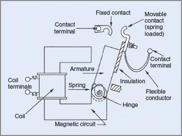
Figure 1 Operating parts (components) of a contactor
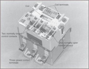
Figure 2 Typical contactor diagram
Contactors may have many contacts, but those in use in power work seldom have more than six. In most contactors there are at least three power contacts.
These contacts are designed to carry the full rated current of the contactor. When used for motor starting duty they are designed to carry five times their rated current for a short time.
The other contacts on the contactor are often termed ‘auxiliary contacts’, or sometimes ‘control contacts’. While one or two of them might be able to carry full load current, in most circuits they only carry control current, which may be in the order of about 100 mA.
Drawing Contactors in Circuits
In terms of symbols AS/NZS 1102 makes no real distinction between power contacts and control contacts. It merely provides two symbols labelled ‘form 1’ and ‘form 2’. In the interests of clarity and to avoid any possible confusion, many use the former for control contacts and add a small circle (see Figure 3), with form 2 contacts for the power part of the circuit. Individuals have their own preferences and make their choice accordingly.
See Figure 3 for the different types of contact symbols. Form 1 contacts and contactor symbols are used extensively throughout this material.
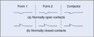
Figure 3 Symbols for contacts and contactors
Both power and control contacts may be either ‘normally open’ or ‘normally closed’. When using the word ‘normal’ it is meant that the contactor is not energized (i.e. power is not applied to the coil). When the contactor coil is energized, the contacts change their state. Normally open contacts close, and normally closed contacts open. In drawings they are always drawn in the de-energized state. The operation of contact symbols (whether opening or closing) is always considered to be in a clockwise direction.
Some contactors may have contacts that are ‘timed’. These timed contacts will close, or open, after a designated time (say, 5 seconds). The timing device may be mechanical or electrical. When electrically timed contacts are required, quite often a timing relay is used.
Timing relays are often connected in parallel with the coil of a contactor and may be adjusted to open or close contacts. Any timed contacts are designated by a special symbol. This takes the form of a semicircle to indicate the contact is slowed down in operation.
Timed contact symbols (off, on delay) of various forms are shown in Figure 4.
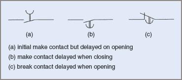
Figure 4 Various timed contact symbols
Some contactors (or relays) are inherently timed by their construction. That is, they close their contacts sometime after they are energized. These relays are drawn with two diagonals in a rectangle on one end of their coil symbols.
Some relays are slow to release after de-energization and these are designated with a filled-in rectangle on one end of their coil symbols.
The symbols for the three types are shown in Figure 5 overleaf. Normally this type only operates in DC circuits.
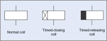
Figure 5 Normal and timed relay coils
Schematic circuits may have no bearing on their actual physical placement or arrangement in a circuit. Contactors may be drawn in circuits in a number of ways. One way is illustrated in Figure 6(a), which shows a contactor with its operating coil and all its associated contacts.
The broken line enclosing the components indicates that they are all part of the one assembly. This type of attached representation is seldom used in schematic circuits because it does not lend itself to a logical circuit arrangement.
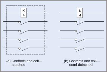
Figure 6 Symbolic representation of coils and contactors
A second method is to indicate by a dashed line that the contactor coil operates the contacts joined by the line. This method is sometimes seen in diagrams, especially when the components on the contactor are close together or in line, in a diagram. This method of semidetached representation is illustrated in Figure 6(b).
The most common method is termed ‘detached representation’. In this convention the contactor coil is not only labelled with the contactor designation but also with the number of contacts it operates (see Figure 7).
The contactor is designated as K and, in the coil symbol, the K1/4 indicates that there are four associated contacts. Sometimes the coil designation is placed beside the coil symbol. In this case there are three normally open power contacts, and one normally open control contact. However, there could be more or less contacts, and some could be normally closed and some could be timed.
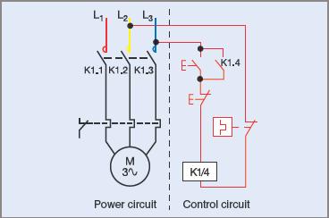
Figure 7 Motor starter circuit—detached representation
It can be seen that the detached representation makes the diagram easier to read. The broken line indicates that all three contacts close simultaneously. Power is supplied to the motor when the three power contacts, K1.1, K1.2 and K1.3 close.
Also in the power circuit are three symbols indicating that they are thermal overload detectors. If an overload occurs they will cause an associated contact to open. The colored lines representing the power conductors have been drawn thicker than the control conductor lines. This method differentiates between power and control circuits. A broken line is shown here separating the two parts of the circuit but it is not a regular practice.
Connected to two of the power lines are two control conductor lines. This circuit uses line voltage for the control circuit. To start the motor, press the start button. The symbol indicates that when the button is released, the switch contact will open again. Current passes to the coil through the normally closed stop push-button switch and energizes the coil of the contactor, K1/4.
It is not regular practice to designate the start and stop push-button switches unless there is a special need. Just the nature of the symbols is enough to show that a normally open push-button switch is a start switch and a normally closed one is a stop switch.
The moment the start switch is pressed K1/4 is energized, which then operates all K1 contacts. In this case they are all normally open contacts so they all close. K1.1, K1.2 and K1.3 supply power to the motor allowing it to start up. K1.4 takes the place of the start push-button switch when the start push-button is released.
Pushing the stop push-button switch opens the circuit to coil K1/4 and all the associated contacts open. The motor then stops and cannot be re-started until the start push-button switch is again pressed.
If an overload condition occurs, the thermal overload detectors open the overload contact and again the motor will stop. Some thermal overload relays are self-setting, while others must be reset before the motor can be started.
The circuit layout with the flow of energy and sequence of events moves from left to right and top to bottom. All components have been spaced across the drawing and kept in line as much as possible. Any drawing should be laid out in this manner, even if it is only a pencil sketch. It makes it much easier to read and interpret at a later date.
Contactors and Relays Key Takeaways
Understanding the construction, operation, and symbolic representation of contactors and relays is essential for anyone involved in electrical engineering, automation, or industrial control systems. These components serve as fundamental building blocks in the design of circuits that control motors, lighting, and various other loads. Their ability to manage high currents (contactors) or provide precise control signals (relays), along with features like auxiliary and timed contacts, allows for flexible and safe circuit operations. Proper schematic representation and knowledge of their behavior under energized and de-energized states are critical for troubleshooting, maintenance, and system design.