The article discusses the operation, causes, and dangers of circuit breaker arcing, including overcurrent and short circuit conditions. It also explains arc interruption mechanisms, restrike risks, the importance of arc chute maintenance, and how maximum total clearing time impacts electrical system safety and incident energy.
Circuit breakers are switches designed to open and close circuits. They may be operated manually or automatically through the use of overcurrent protective devices (OCPDs). The automatic operation of a circuit breaker occurs when there is an abnormal condition such as an overcurrent or short circuit.
For example, an overcurrent condition can occur when a coupling between an electric motor and a pump is misaligned. The misalignment causes the motor to work harder to overcome the increased mechanical resistance. As a result, the motor draws more than the rated current. If allowed to continue, this overcurrent condition can cause the motor to overheat and the insulation to fail due to thermal degradation. These conditions create current that is several times the full-load rating of the circuit breaker.
Overcurrent
Overcurrent is electrical current in excess of the equipment limit, total amperage load of a circuit, or conductor or equipment rating. An overcurrent condition is not a short circuit. A short circuit is an unintentional connection of two ungrounded conductors that have a potential difference between them.
Short Circuit
A short circuit occurs when there is an unintentional grounding of an energized conductor, usually resulting in an arc flash. Short circuits can be four or more times the full-load current of a circuit.
When a circuit breaker opens to clear a system short circuit, an arc is also created between the opening contacts, which are located inside the arc chute. The arc between the circuit breaker contacts occurs due to the ionization of air, just as the air is ionized during a system short circuit.
In short-circuit conditions, the arc flows from an energized conductor/component to ground or possibly phase-to-phase. It remains a conductor, and short-circuit current continues to flow through it as long as the air is ionized. This ionization of air occurs when electrons are knocked out of their orbits around the molecules of air by the extreme heat of an electric arc. Since the electrons are no longer attached to air molecules, the electricity uses the free electrons as a path across the arc chute. Circuit breakers use arc chutes to deionize the air and interrupt the flow of short-circuit current.
Arc Interruption
An arc chute (arc extinguisher) contains, cools, stretches, and deionizes and extinguishes the arcs between contacts. This occurs within 1/10 of a second (six cycles) or less and is critical to the safe operation of the circuit breaker and power system. A circuit breaker can fail to clear (extinguish) an arc due to the following reasons:
• Arc chute component is defective
• Arc chute is contaminated with moisture or carbon residue from previous operations
• Mechanical failure of the operating mechanism in that it opens too slowly or even fails to open
When a circuit breaker does not clear the arc, the arc re-establishes itself and a restrike occurs. A restrike is a resumption of current between the circuit breaker’s contacts if the circuit breaker fails to clear an arc. See Figure 1.
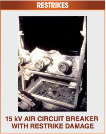
Figure 1. Circuit breakers can become permanently damaged by restrikes.
One common problem, especially with older arc chutes, is that arc chutes can absorb moisture. Older arc chutes are made of materials such as ceramic, asbestos, and celluloid or phenolic plastic resins that tend to absorb moisture.
When a circuit breaker attempts to interrupt an arc, the moisture absorbed by the arc chute is released into the arc chute as steam. Small amounts of moisture can cause catastrophic restrikes. To help prevent restrikes, arc chutes can be dried by placing heat lamps around them while they are covered with a tarp or by using an industrial oven. Both methods take several hours or days, depending on the saturation of the arc chute.
Maximum Total Clearing Time
Maximum total clearing time is the time required to interrupt an arc and is considered to be from when the arc starts until it is completely extinguished. This characteristic is used to properly coordinate power systems so that they will trip in the right sequence (selective tripping).
During selective tripping, the device closest to the load operates first. If that device does not operate, due to mechanical or electrical failure, then the next device upstream operates to clear the fault. If that device does not operate, then the next device upstream operates and so on. This process is sometimes referred to as “cascading.”
Improper maintenance can also cause circuit breakers to malfunction, either by slowing their operating speed or by preventing them from operating. When this occurs, arc flash studies and their labels do not correctly reflect the true incident energy that would be received by a worker if exposed to an arc flash.
Typically, incident energy is proportional to time. If the duration of operation doubles from two cycles to four cycles, the incident energy received by the technician also doubles. The personal protective equipment (PPE) and arc-rated clothing will be inadequate. The situation may result in serious injuries or a fatality. This aspect of incident energy makes the maintenance of OCPDs a matter of safety not just maintenance.
The maximum total clearing time includes the amount of time it takes for the circuit breaker to clear the arc, the operating time of the OCPD and any other auxiliary relay that may be part of the circuit.
The incident energy is directly affected by the speed of the circuit breaker’s operation, the distance which its contacts must travel and the ability of the arc chutes to extinguish the arc according to the manufacturer specifications. Changing one of these factors from its design specifications can cause major problems when the circuit breaker must operate at or near its interrupting rating.
Another factor that must be considered for arc interruption is the zero cross- over point of the alternating-current sine wave. The zero crossover point is the point at which current alternates and begins to change direction. See Figure 2.
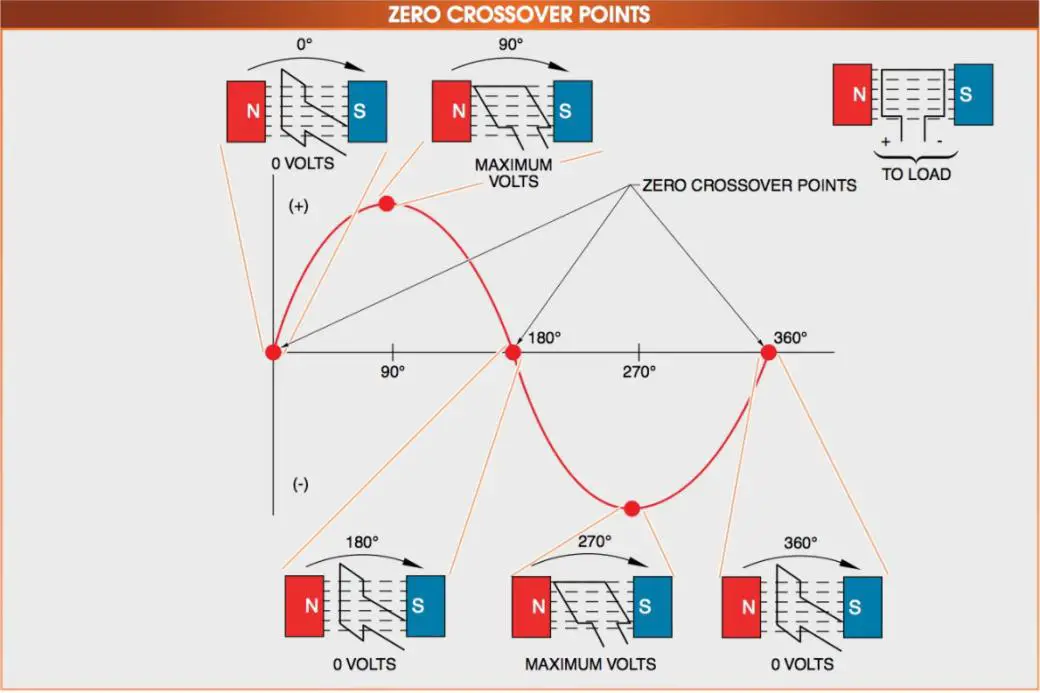
Figure 2. The zero crossover point is the point where current alternates and begins to change direction and the only point where an arc can be interrupted.
As the generator armature in Figure 2 begins to rotate, it is at a zero crossover point (0°). Rotating the armature to the 90° position causes the number of lines of flux cutting the armature to increase to its maximum amount, which produces the maximum voltage and current. As the armature continues to rotate, the number of lines of flux being cut decreases until it is at the 180° position. At this position, no lines of flux are being cut, and it is again at a zero crossover point.
It is only at a zero crossover point that the current can be interrupted, so the arc must be stretched, cooled, and then, at zero crossover, extinguished. The approximate maximum total clearing times for a circuit breaker may vary, depending on the circuit breaker type. See Figure 3.
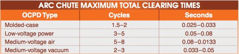
Figure 3. Maximum Clearing Times in Different Circuit Breakers
Safety Fact
With alternating current (AC) circuits, arcs are extinguished at a current of zero (0 V) when the AC voltage applied across the arcing contacts reverses polarity.
Circuit Breaker Arcing Key Takeaways
Understanding circuit breaker arcing—its causes, behaviors, and interruption methods—is essential for ensuring the safety and reliability of electrical systems. The proper functioning of arc chutes, timely arc interruption, and maintaining maximum total clearing time are critical to minimizing incident energy and preventing catastrophic equipment failure or personal injury. These concepts are especially important in real-world applications such as industrial power systems, commercial facilities, and utility networks where high fault currents are common. Proper design, maintenance, and coordination of circuit breakers not only safeguard equipment but also protect workers, emphasizing their vital role in electrical safety and system performance.