In this article, we have covered induction motor speed control methods along with their circuit diagrams in details:
Speed Control by Changing the Number of Poles
Speed Control by Changing Frequency
Speed Control by Kramer Method
Electronic Frequency Control
Torque is produced in an induction motor through the interaction of two magnetic fields. The first rotating magnetic field is created by currents flowing in the stator windings. This rotating field cuts the conductors in the rotor and induces a voltage in them. The rotor voltage causes currents to flow in the rotor and produce a second magnetic field.
The two magnetic fields interact with each other and cause the rotor to rotate in the direction of the rotating stator field. It accelerates to approximately 96 per cent of the speed of the rotating stator field. This 4 per cent difference in speed on full load is the slip speed. Without slip, an induction motor cannot develop torque.
The speed of an induction motor is always governed by the rotating magnetic field in the stator. This stator field always rotates at a synchronous speed governed by two factors:
1. The number of pairs of poles
2. The frequency of the applied voltage.
The synchronous speed can be found from:
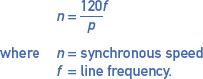
$$n=\frac{120f}{p}$$
$$\textrm{where n}=\textrm{synchronous speed}$$
$$f=\textrm{line frequency} $$
The number 120 is derived from the product of the number of seconds in a minute and the fact that magnetic poles always come in pairs. The other two quantities are called variables.
It is important to note that there are only two variables.
If the frequency increases, the speed increases:
$$n\propto f$$
If the number of poles increases, the speed decreases:
$$n\propto \frac{1}{p} $$
These two basic principles are the only factors that can affect the change in speed of an induction motor, although the methods adopted to achieve this are many.
Speed Control by Changing the Number of Poles
Changing the number of poles in a stator winding always involves an abrupt step change from one speed to another. On a 50 Hz supply, a two-pole induction motor will rotate at 3000 rpm (ignoring slip speed). If a change is made to a four-pole stator, the speed will quickly change to 1500 rpm.
The change in speed can transmit minor transients into the supply lines. With larger induction motors, a short time delay should be introduced when changing from one winding to the other.
The most common method is to design windings that can be interconnected to change the number of poles. It is invariably a 1:2 ratio, that is, a two-pole winding converts to a four-pole winding, or a four-pole to an eight-pole winding, and so on.
Figure 1(a) illustrates the principle and connections involved for a four-pole to eight-pole conversion. Only one phase is drawn; small rectangles are used to represent pole-phase groups and the arrows indicate the sense of winding direction. It is necessary that the pole windings be connected in pairs opposite each other as shown.
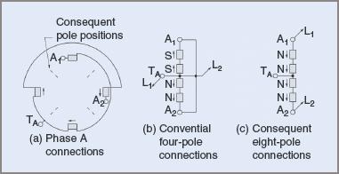
Figure 1 Series-parallel connection for a two-speed induction motor
Note that the center-tap (T A) of the winding has been brought out so that it can be accessed externally. In Figure1 (b), the four pole-phase windings have been redrawn in a vertical line. If A1 and A2 are bridged and connected to line L2 and the center-tap T A connected to line L1, the motor will have four conventional poles as indicated by the arrows.
In Figure 1(c) the bridge has been removed. A1 is reconnected to line L1and A2 left connected to line L2. As indicated by the arrows, the current flows through all four pole-groups in series and all give the same polarity, for example, as shown there would be four north poles.
The magnetic flux is diverted in the stator and exits between the north poles as indicated by the broken lines. The resulting magnetic circuit of the induction motor is that of an eight-pole machine.
To get around this 1:2 ratio limitation, some stators have been designed to accommodate two electrically separate windings. Only one winding is used at a time. These windings need not be in the ratio of 1:2 but can be any reasonable relationship. For example, one winding could be a two-pole winding, the other a six-pole winding.
Activating the two-pole winding would cause the induction motor to rotate at 3000 rpm. During this period the other winding, if not connected in star configuration, must have the delta bridges open-circuited to prevent induced currents flowing in the unused winding. When provided with a suitable switch, the windings could be exchanged without stopping the motor or its coupled machine. The induction motor would then change speed to 1000 rpm.
Step speed control with pole amplitude modulation (PAM) is a rather lesser known system. It was developed for close speed ratios, such as changing a four-pole to a six-pole and an eight-pole to a ten-pole. It relies on the principle of unequal coil groupings within the induction motor when manufactured. Connections are made with special contactors to control speed steps.
PAM windings are covered by copyright but can be manufactured under license. PAM motors are made as small as 0.5 kW but have been made in sizes up to 7 MW.
Speed Control by Changing Frequency
One important aspect of this method of speed control is that, at higher frequencies, the standard induction motor runs at speeds well above the base design value. At increased speeds, air circulation is improved, resulting in improved cooling.
Better cooling permits higher current densities to be used, even though there is increased friction and windage losses due to higher speeds. There are also increased iron losses due to the higher frequencies. At higher frequencies, the impedance of the windings is also increased and, to ensure a constant flux density in the air gap, a higher supply voltage is required.
At constant flux density in the air gap, torque is proportional to current flow.
Since power is dependent on both torque and speed, it can be seen that the power output of the induction motor increases at a faster rate than the speed increase.
Increasing the frequency of a complete plant would ensure all motors ran at a faster speed and this might not always be desirable. Decreasing the frequency would ensure that all motors ran more slowly, and produce the same undesirable result.
In general then, frequency changing as a method of speed control is limited to specific machines or groups of machines, as in a series of transport rollers in a steel mill.
There are two main methods for frequency changing. The first uses rotating machinery to achieve the desired result. It is expensive, although less efficient than some other methods, but experience has shown it to be extremely reliable, with minimal maintenance problems. Therefore, it is still in considerable use.
The second method uses electronic switching to synthesize an irregular-shaped alternating current wave from DC. It is a comparatively new procedure and has become very popular.
Rotating Machinery for Frequency Control
One common motor control system is the Schrage motor, where the speed is altered by adjusting the brush positions for each phase.
Figure 2 illustrates another method for speed control. In this instance, it is the Kramer method for controlling the speed of a wound-rotor induction motor. It can be seen that four rotating machines are used to control the speed of one motor.
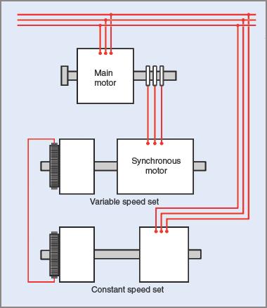
Figure2 Kramer drive using rotating machines
The system can only be justified economically for extremely large induction motors or integrated groups of motors in heavy industry. Where Schrage motors have practical limitations, the Kramer system can be built in megawatt ranges. Reliability and minimal maintenance have been well established in both systems.
Wound-Rotor Induction Motors
The slip in any induction motor is proportional to the rotor copper losses. In a wound-rotor Induction motor, the rotor resistance can be varied with the addition of external resistance, so rotor copper losses and speed can be adjusted with a controller.
Because rotor current is proportional to the developed torque, it would follow that rotor losses would vary with the applied load, thereby affecting the speed. This method of speed control has the characteristic of a variation in speed for a variation in load; that is, increasing the load causes the speed to decrease, while decreasing the load results in a speed increase.
For this reason, speed control of a wound-rotor induction motor by varying the rotor resistance is satisfactory only for a steady load. Speeds lower than half full-load speed are not practical and increased losses at lower speeds lead to high operating temperatures, which might exceed the ratings of the induction motor. Motor efficiency is poor, speed regulation is poor and the external resistances consume wasteful power.
Various methods have been tried for speed control. The two most common are:
1. Unequal voltages applied to stator windings
2. Unequal resistances inserted in rotor windings.
Unlike the rotating machinery systems described above, these speed changes are step changes. Probably the most common application is in the hoist and lowering mechanism of overhead cranes.
Electronic Frequency Control
The rapid advances made in semiconductor technology have led to much more efficient and effective means of altering mains frequencies. Figure 3 shows block diagrams of inverter drives.
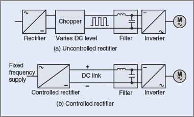
Figure 3 Block diagrams of variable frequency motor drives
The three-phase supply is first converted to a DC supply. There are at least two possible conversion methods in general use. One is to use a fixed or uncontrolled rectifier circuit and the other is to use a controlled rectifier circuit. Each type of circuit has its advantages and disadvantages.
Uncontrolled Rectifiers
The output voltage from an uncontrolled rectifier circuit (e.g. a bridge rectifier) is governed by the AC input voltage. The DC output is then fed to a ‘chopper’ circuit. Its function is to switch the DC on and off at a rate higher than the fundamental frequency of the supply. The on/off action adjusts the average DC voltage level supplied to the inverter.
Figure 3(a) shows the approximate square-wave shape of the chopper output. This is then fed through a filter circuit to remove as many transients and spikes as economically reasonable and it then becomes the input to the inverter circuit.
Controlled Rectifiers
A controlled rectifier circuit such as one using silicon-controlled rectifiers with phase control has the advantages of a fast response, relative cheapness and the ability to maintain a regenerative action of feeding power back into the mains. It has the disadvantage of operating at a lagging power factor.
Because the DC from the controlled rectifier does not have to be fed through a chopper circuit, it tends to be less complicated and possibly a more efficient circuit. The output is generally filtered before being supplied to the inverter section (see Figure 3(b)).
To maintain optimum performance of an AC induction motor with a varying frequency supply, it is necessary to maintain the designed magnetic flux conditions in the magnetic circuit of the induction motor. This is generally achieved by ensuring that the ratio of supply voltage to frequency is kept constant. Any change in frequency must then be accompanied by a change in voltage, that is:
$$V/f=K$$
The actual type of circuit and the control method depend largely on the induction motor application. A balance has to be selected between the desired factors of speed, torque and power.
Other factors involved are the type of circuits in the unit and whether the final output sends a signal of its own performance to the unit’s input for monitoring and self-adjustment of the unit.
Summarizing:
A. The Inverter Controls the Output Frequency.
B. The Motor Voltage Is Set by The DC Link Voltage.
C. Other Parameters Such as Current, Slip and Slip Compensation Minimum and Maximum Speeds Can Be Controlled.
D. Acceleration and Starting Current Ramps Up and Down Can Be Controlled.
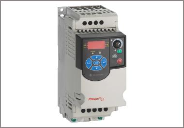
Figure 4 Typical electronic frequency control unit for an induction motor
Methods of induction motor speed control are listed in Table 1.
Table 1 Methods of Induction Motor Speed Control
| Type of motor | Speed characteristic, no load to full load | Method of speed control |
| AC, squirrel cage, multi-speed | Speed drop up to 5% from or two or more initial speeds | Pole changing. Windings of different pole numbers, or reconnect one winding to change the pole number |
| AC, squirrel cage, single-speed | Speed drop up to 15%, depending on design | Primary voltage control. Stator frequency control at constant volts per cycle |
| AC, slip-ring | Speed drop up to 50%, depending on rotor resistance | Secondary resistor connected to slip-rings. Machine and solid-state conversion feedback of rotor power |
| AC, synchronous | No speed drop. Speed set by stator frequency | Adjustable frequency from motor generator set or solid-state frequency converter |
Induction Motor Speed Control Key Takeaways
The various methods of induction motor speed control discussed—such as changing the number of poles, altering the supply frequency, using the Kramer method, and employing electronic frequency control—are critically important because they provide practical means to precisely regulate motor speed for diverse industrial and commercial applications. These control techniques enable motors to operate efficiently under different load conditions, improve process accuracy, and reduce energy consumption. For instance, pole-changing methods are useful for applications requiring distinct speed steps, while frequency control offers smooth and wide-range speed adjustment essential for conveyor systems, pumps, and fans. Electronic frequency control, in particular, allows fine-tuned speed and torque management, contributing to enhanced performance and longevity of motors in modern automation.