In general, DC motors require the same sort of protection as AC motors. Thermal and magnetic overload protection is just as applicable to DC motors as it is to AC motors. Fuses are an essential part of both DC and AC circuits.
There are, however, some items of protection that apply specifically to DC motors.
Field Failure Protection
Extreme weakening or complete loss of a shunt field is an unlikely event, but it is a possibility that exists and precautions need to be taken. The complete or partial loss of the shunt field results in a sharp reduction of generated back EMF. This causes a big increase in armature current, often without a corresponding rise in torque.
When a motor is coupled to a load, it might be unable to increase the speed of the load and high currents continue to flow, thus damaging the armature windings.
If the motor can shed the load or is unloaded, high speeds occur. This can result in armature windings being thrown out of the slots by centrifugal force.
Commutator segments can also be thrown out of their assembly. Where motors are coupled to loads subject to the forces of gravity, loss of motor control allows the load to fall out of control. Damage and injury can occur.
To prevent these incidents a field-failure relay is used. It consists of a pair of normally open contacts with the activating coil connected in series with the shunt field. The normally open contacts of the field-failure relay are connected in series with the main contactor.
While field current flows, the relay is activated, the contacts are closed, and power can be applied to the armature by the main contactor.
In the event of a field failure, the relay contacts open, allowing the main contactor to drop out and isolate the motor. Figure 1 shows part of a control circuit with a field failure relay in circuit.
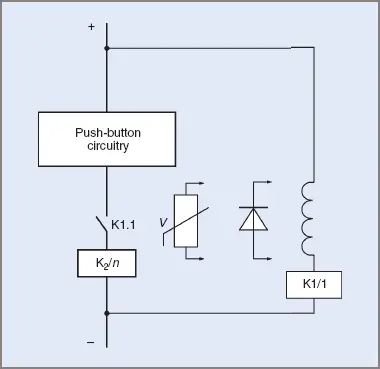
Figure 1 Field failure relay connections
Field Discharge Protection
When disconnecting the shunt fields of many DC motors from the supply, the induced voltages created as the magnetic field collapses can be high enough to break down the insulation of the windings. An electric circuit should be connected in parallel with the field to enable this converted energy to be dissipated without damage to the circuit.
In Figure 1, two forms of protection are shown, although only one need be used. Where the polarity of the field supply is constant, the reverse-connected diode is sufficient protection for the field circuit.
The diode has to have a voltage rating high enough to withstand line voltage in the non-conducting state and it has to have a current rating high enough to avoid being damaged by the discharge currents.
Where the polarity of the field supply is subject to reversal, the second type of protection is used. It consists of a special compound that has a high resistance at normal voltages.
When the rated voltage is exceeded, the resistor reverts to a low resistance and allows the energy to dissipate. When the high voltage is removed, the unit changes back to a high resistance. The components are made under several trade names and are also used for lightning protection.
Over-Voltage Protection
Although included here as a protection method, over-voltage protection is more applicable to DC generators. Generators subject to a wide range of speeds when driven by a prime mover are capable of producing high voltages. The output voltage can be three to four times normal voltage while under the influence of full-strength magnetic fields.
Automobiles, aircraft and similar engine-driven units have generators driven either by belts or directly by solid drives. They are an accessory and quite separate from the primary drive intention. The engines are necessarily subject to a wide range of speeds, so it follows that the generators will also have a wide speed range.
Since the generator is expected to produce a useful output at comparatively low speeds, it will need some form of voltage control when driven at high speeds. Many systems for regulating the output voltage have been used but all rely on controlling the field current of the generator to control output voltage.
Probably the most common form of voltage control is a quick-acting relay sensitive to voltages above a certain level. Older style voltage regulators often had a voltage-controlled relay that inserted resistance in the field circuit when the relay was activated.
In more modem units, voltage sensitive semiconductor components were introduced. These conduct at specific voltages and reduce the current flowing through the field.
Depending on circuit configuration, the unit can insert resistance into the circuit or divert the current around the field when voltage levels exceed a set value. The method is accurate and can also be combined with current-controlled sections.
Many mobile units use alternators with rectifier units to produce direct current. A similar control method is used for over-voltage protection since the alternator field is excited with direct current.