The article outlines various AC power control methods, including switched control, rheostat control, voltage control using Variacs and inductors, and thyristor-based control. It highlights each method’s operational principles, efficiency, suitability for different applications, and associated advantages and disadvantages.
A wide variety of methods has been developed to control the AC power in a load. Some have found widespread use, while others are particularly specialized in their application.
Switched Control
Rheostat Control
Voltage Control
Thyristor Power Control
Load power may be controlled by a switching method, where the load is turned on and off; or by linear methods, where the load power is controlled by providing continuous or infinite control of load voltage.
Switched Control
In principle the switching method is the simplest method of controlling power. As shown in Figure 1, control consists of a switch either to connect or to disconnect the load from the supply. Control is limited to a simple on/off action. The AC power dissipated by the load is determined by the load current and voltage.
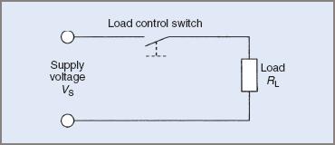
Figure 1 Switched load control
This form of control is limited to situations where on/off control is all that is required, for example, controlling the temperature of stored water where the switch is actually a thermostat and cycles the load according to changes in temperature.
A variation of switched control is simmerstat control. A simmerstat is a switch that is cycled on and off by a small heating element inside it. The actual switch contact is mounted on a bimetal strip that bends as its temperature changes, opening and closing the switch.
The average AC power dissipated by the load is controlled by the relative on/off times of the simmerstat. The switching action is independent of the power actually being dissipated in the load. This may be a disadvantage in some situations.
The simmerstat is widely used for the control of heating elements such as the hotplates on electric ranges and electric blankets.
The advantages of this method are that it is simple and relatively inexpensive. The disadvantages are that it provides coarse control, is relatively unreliable and inaccurate, and suffers from contact wear and/or fatigue.
Rheostat Control
Rheostat control uses a series-connected rheostat (variable resistance), as depicted in Figure 2, to control load power. As resistance is introduced in series with the load, the load voltage, and hence AC power, is reduced. The reduction in load voltage is caused by the voltage drop across the rheostat.
AC Power may be controlled from a very low value, up to full power. However, for a wide range of control the rheostat may be physically very large; it may in fact be larger than the load. To control the load, power must be dissipated in the rheostat. This is a power loss and results in poor efficiency at low load settings. When the load power is reduced to 50 per cent, the power dissipated in the rheostat is equal to the load power.
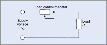
Figure 2 Rheostat load control
For example, assume that the load in Figure 2 has a resistance of 10 Ω and the supply voltage is 100 V. If the rheostat is set to 5 Ω, determine the load power, input power and efficiency.
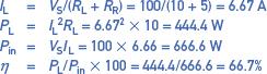
$$ I_{L}=V_{S}/\left ( R_{L}+R_{R} \right )=100/\left ( 10+5 \right )=6.67A$$
$$P_{L}=I_{L}^{2}R_{L}=6.67^{2}\times 10=444.4W$$
$$P_{in}=V_{S}I_{L}=100\times 6.66=666.6W$$
$$\eta =P_{L}/P_{in}\times 100=444.4/666.6=66.7\textrm{%}$$
If the rheostat in Figure 2 were set to 10 Ω, the load power would be further reduced to 250 W. The efficiency would also decrease: in this example, to 50 per cent. As the load power is reduced even further, the efficiency also decreases.
This form of control is widely used in equipment of older design. Owing to its low efficiency and generally poor performance, it has now been largely superseded by more modern methods.
Apart from poor efficiency, an undesirable aspect of this method is the manner in which the load voltage varies if the load current varies. This is termed ‘poor load regulation’ and may be overcome by using automatic voltage regulators, but this becomes very expensive when the load power is high and still does not overcome the poor efficiency of the method.
This method of AC power control has the advantage that it is very simple. The disadvantages are that it is very inefficient, bulky, very expensive (when the running costs are taken into consideration), and has poor load regulation.
Voltage Control
This method controls the load power in the same manner as rheostat control that is, by varying the load voltage, but uses either a Variac or a tapped inductor. These methods are suited only to AC supplies and loads. The use of the Variac or the tapped inductor overcomes the poor efficiency of the rheostat method.
Variacs and inductors are very efficient devices compared with rheostats. A Variac is a form of transformer. It is a variable autotransformer. These devices are efficient but they have the disadvantage that they are bulky, heavy and expensive, particularly where the load power is high.
AC Power may be controlled from zero to rated power. Figure 3 shows a Variac connected to control load power.
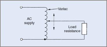
Figure 3 Variac power control
This method is very efficient (efficiencies in excess of 90% can be expected), offers fine control, and displays quite good load voltage regulation. Owing to the high cost and mass of the Variac, it is usually limited to low-power applications. The sliding contacts in the Variac may also have wear problems.
The tapped inductor method is a variation of the adjustable autotransformer system. It has a limited number of adjustments and effectively adds impedance in series with the load. The method is more efficient than the rheostat method, but still does not provide very good load regulation.
Figure 4 shows a tapped inductor connected to control the AC power in a load.
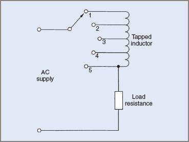
Figure 4 Tapped inductor power control
The method is used for the speed control of ceiling fans and other low-power applications. Control of high values of load power with this method would necessitate large, expensive inductors.
The advantages of the method are that it is simple and efficient, while it has the disadvantages that it is costly for medium to high power loads, has poor load regulation and provides control only in discrete steps.
Thyristor Power Control
Thyristor control has largely superseded all other methods of AC power control. It offers efficient and cost-effective control of power in most applications from very low to very high power levels. Figure 5 shows a simplified diagram for a thyristor power controller.
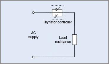
Figure 5 Thyristor AC power control
Thyristors are a family of electronic devices designed specifically to provide power-control functions. They are in effect controlled switches. Thyristors are turned on by a pulse of gate current, the gate being the control lead on the device. Once turned on, these devices offer very little resistance and hence dissipate very little power, resulting in high efficiencies.
Thyristor controllers achieve efficient AC power control by one of two methods:
1. Phase-control—the AC waveform is ‘chopped up’ to achieve varying values of load voltage. The load voltage waveforms are no longer sinusoidal, but in many applications this is not a problem. The variable voltage is obtained by delaying the ‘triggering’ of the thyristor and hence reducing the conduction time.
An advantage of this method is that it may be applied to AC or DC loads being supplied from an AC supply. It has the disadvantage that it produces radio frequency interference (RFI) when the thyristor is triggered. The waveforms in Figure 6 represent typical load voltage waveforms supplied from a phase-controlled thyristor controller.
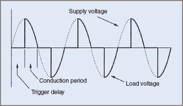
Figure 6 Phase control load voltage waveforms
2. Zero voltage switching— was this method of control devised to overcome the RFI generated by phase-control techniques. It operates in a similar manner to a simmerstat in that the load voltage is controlled by controlling relative on/off times. In this case, however, the on and off times will be measured in cycles.
For high power, the thyristor will be turned on for a larger number of cycles than it is off, and the reverse applies for low power. To minimize RFI, the thyristor is switched as the supply voltage crosses zero or is at zero volts. Unlike simmerstat control, this method may employ feedback from the load to provide accurate control. This method is suited only to resistive loads such as heating elements. It is unsuited to inductive loads. Typical waveforms are shown in Figure 7.
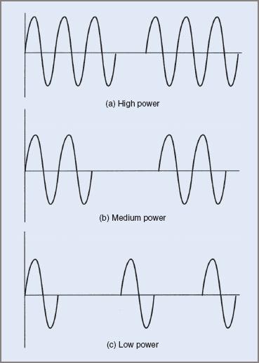
Figure 7 Load waveforms for zero voltage switching
Thyristor controllers are widely used in the control of AC power in industrial and domestic applications. A thyristor controller may be designed and constructed to control a lamp in a domestic situation or to control loads such as a 1500 kW motor in industry.
Thyristor controllers have the advantage that they are relatively inexpensive (taking running costs into account), highly efficient, reliable, adaptable to most situations, have good load regulation, and are relatively compact.
The disadvantages are that they might require complex trigger or control circuits. Phase-control circuits produce radio frequency interference (RFI) and most controllers produce non-sinusoidal waveforms that tend to generate harmonics in the supply.
The thyristor devices most commonly used to control the power in a load are:
- Silicon-Controlled Rectifiers (SCRs)
- Gate Turn-Off Thyristors (GTO Thyristors)
- Triacs.
Thyristors are switching devices. They are triggered (switched) on by a current pulse through a gate terminal. A thyristor must be accompanied by a suitable triggering circuit in which the active component is known as a ‘trigger device’. Trigger devices are:
- Unijunction Transistors (UJT)
- Programmable Unijunction Transistors (PUT)
- Diacs.
AC Power Control Methods Key Takeaways
The various AC power control methods—ranging from simple switched and rheostat controls to more advanced voltage control techniques and thyristor-based systems—are vital for tailoring power delivery to specific applications. Each method offers distinct advantages in terms of simplicity, cost, precision, or efficiency, making them suitable for different scenarios such as domestic heating, fan speed regulation, lighting, and industrial motor control. Understanding these methods is essential not only for selecting the right control strategy based on performance and cost-efficiency but also for ensuring safety, reliability, and energy optimization in both low-power and high-power systems.