The article discusses how to interpret Zener diode datasheet specifications. It covers key parameters such as maximum power dissipation, maximum current rating, zener voltage tolerance, zener resistance, and derating factor. Understanding these specifications is essential for designing circuits and ensuring the proper operation of Zener diodes in various applications.
Figure 1 shows the datasheets for the 1N5221B and 1N4728A series of Zener diodes. Refer to these datasheets during the following discussion. Again, most of the information on a datasheet is for designers, but there are a few items that even troubleshooters and testers will want to know about.
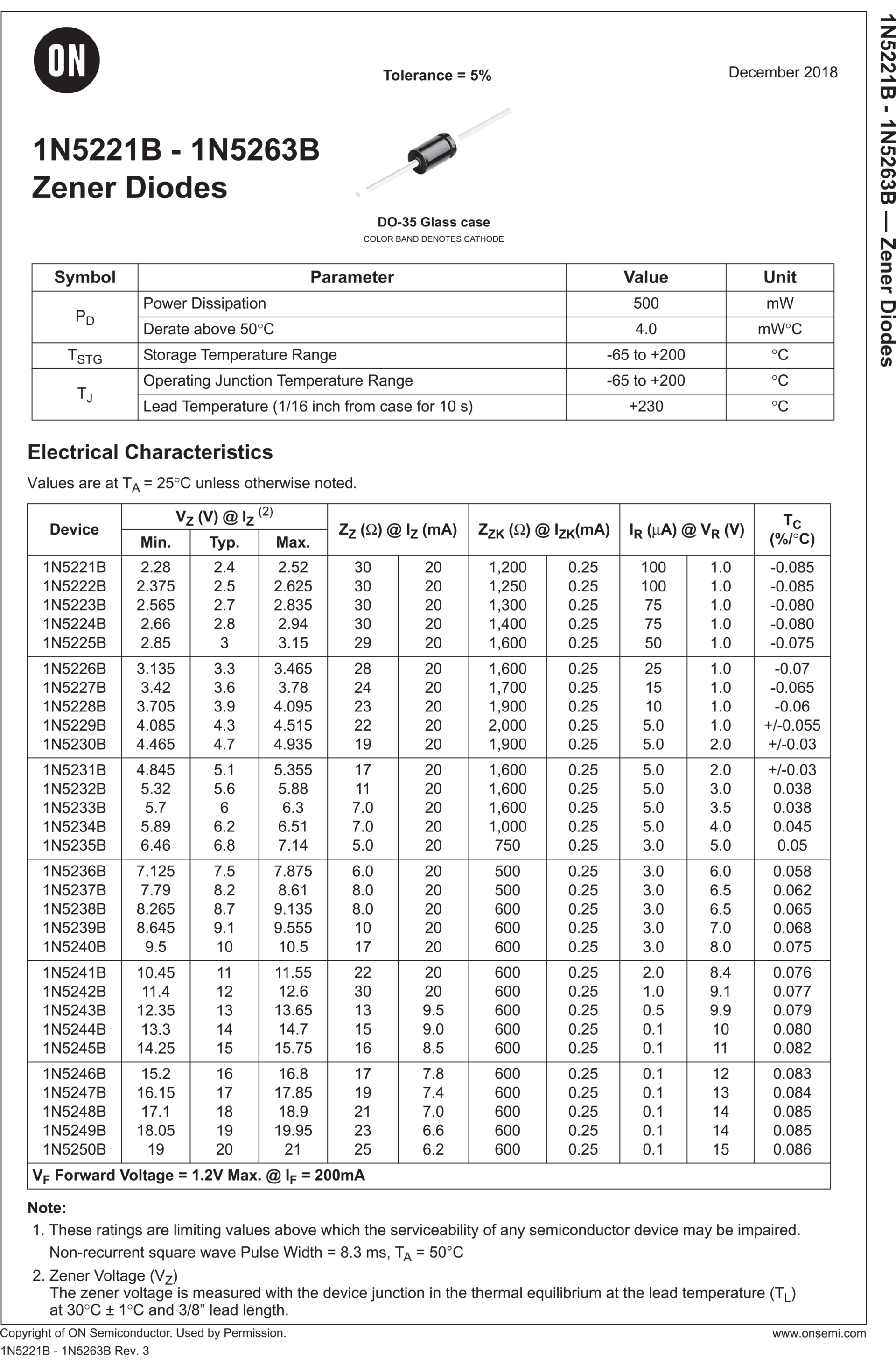
Figure 1(a). Zener diode “partial” datasheets.
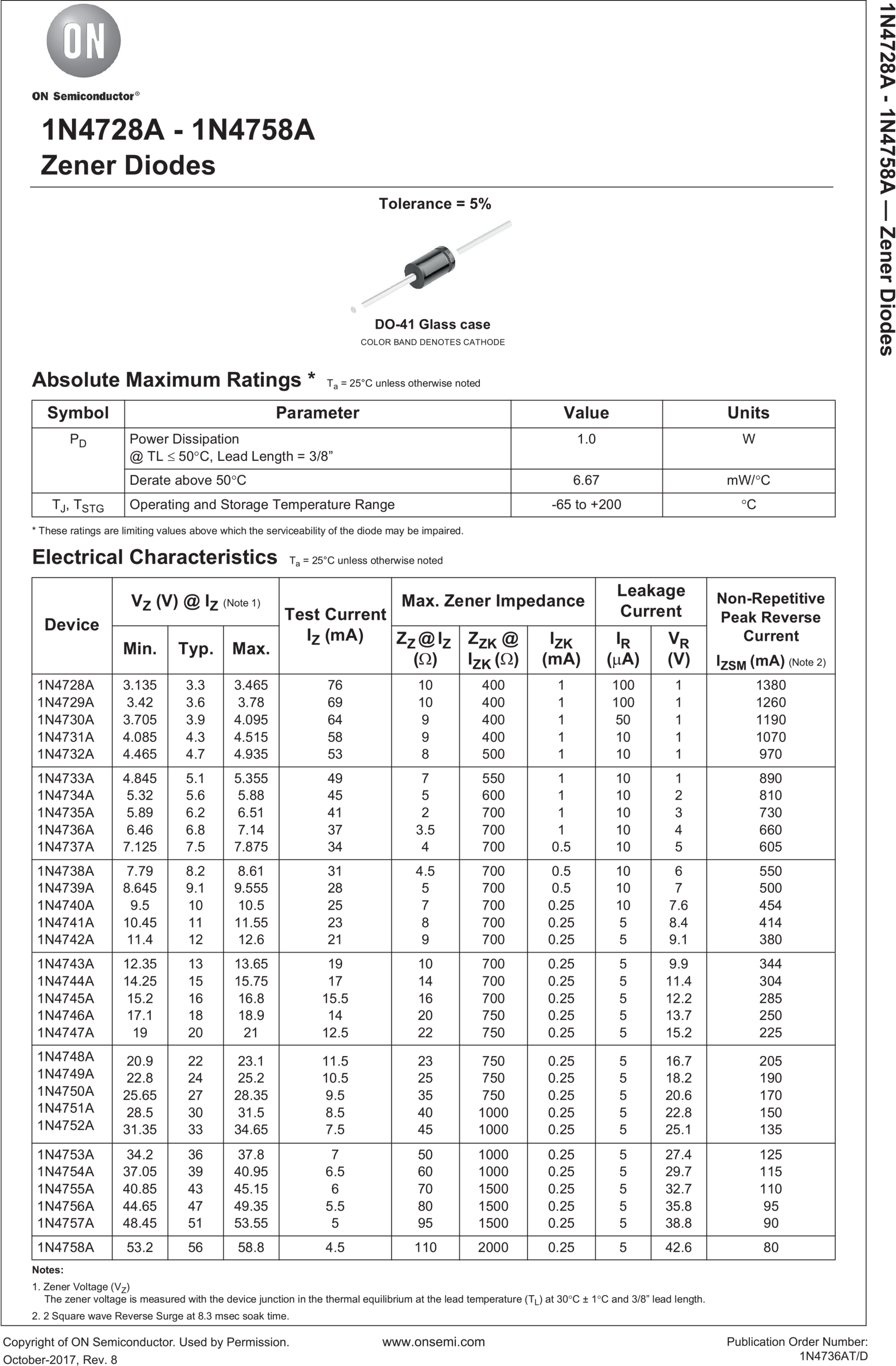
Figure 1(b). 1N4728A-1N4758A Zener Diode Datasheet
Maximum Power
The power dissipation of a zener diode equals the product of its voltage and current:
$$P_Z=V_ZI_Z$$
For instance, if VZ=12 V and IZ=10 mA, then
$P_Z=12V\ \times10\ mA=120\ mW$
As long as PZ is less than the power rating, the zener diode can operate in the breakdown region without being destroyed. Commercially available zener diodes have power ratings from ¼ to more than 50 W.
For example, the datasheet for the 1N5221B series lists a maximum power rating of 500 mW. A safe design includes a safety factor to keep the power dissipation well below this 500-mW maximum. Safety factors of 2 or more are used for conservative designs.
Maximum Current
Datasheets often include the maximum current IZM a zener diode can handle without exceeding its power rating. If this value is not listed, the maximum current can be found as follows:
$$I_{ZM}=\frac{P_{ZM}}{V_Z}$$
Where
IZM = maximum rated zener current
PZM = power rating
VZ = zener voltage
For example, the 1N4742A has a zener voltage of 12 V and a 1-W power rating. Therefore, it has a maximum current rating of
$$I_{ZM}=\frac{1W}{12\ V}=83.3\ mA$$
If you satisfy the current rating, you automatically satisfy the power rating. For instance, if you keep the maximum zener current less than 83.3 mA, you are also keeping the maximum power dissipation to less than 1 W. If you throw in the safety factor of 2, you don’t have to worry about a marginal design blowing the diode. The IZM value, either listed or calculated, is a continuous current rating. Nonrepetitive peak reverse current values are often given, which include notes on how this device was tested.
Tolerance
Most zener diodes will have a suffix A, B, C, or D to identify the zener voltage tolerance. Because these suffix markings are not always consistent, be sure to identify any special notes included on the zener’s datasheet that indicate that specific tolerance. For instance, the datasheet for the 1N4728A series shows its tolerance to equal ±5 percent, while the 1N5221B series also has a tolerance of ±5 percent. A suffix of C generally indicates ±2 percent, D ±1 percent, and no suffix ±20 percent.
Zener Resistance
The zener resistance (also called zener impedance) may be designated RZT or ZZT. For instance, the 1N5237B has a zener resistance of 8.0 Ω measured at a test current of 20.0 mA. As long as the zener current is beyond the knee of the curve, you can use 8.0 Ω as the approximate value of the zener resistance. But note how the zener resistance increases at the knee of the curve 1000 Ω. The point is this: Operation should be at or near the test current, if at all possible. Then you know that the zener resistance is relatively small.
The datasheet contains a lot of additional information, but it is primarily aimed at designers. If you do get involved in design work, you have to read the datasheet carefully, including the notes that specify how quantities were measured.
Derating
The derating factor shown on a data sheet tells you how much you have to reduce the power rating of a device. For instance, the 1N4728A series has a power rating of 1 W for a lead temperature of 50°C. The derating factor is given as 6.67 mW/°C. This means that you have to subtract 6.67 mW for each degree above 50°C. Even though you may not be involved in design, you have to be aware of the effect of temperature. If it is known that the lead temperature will be above 50°C, the designer has to derate or reduce the power rating of the zener diode.
Key Takeaways
Mastering the interpretation of Zener diode datasheet specifications is crucial for engineers, designers, troubleshooters, and testers alike. Key parameters such as maximum power dissipation, maximum current rating, zener voltage tolerance, zener resistance, and derating factor provide vital information for designing circuits and ensuring the reliable performance of Zener diodes in diverse applications. By carefully analyzing and understanding these specifications, professionals can make informed decisions to optimize the performance and longevity of Zener diodes in their electronic designs.