The article provides an overview of various types of power and energy meters, including their operating principles, accuracy, and applications. It also discusses advancements from mechanical to electronic instruments and introduces specialized meters like frequency meters, high-frequency wattmeters, and total harmonic distortion (THD) meters.
Power meters in the times of mechanical instruments required two coils, one for voltage connected across the circuit and one for current to be connected in the circuit so their combined magnetic field would cause the meter to register power. The instrument was reasonably reliable and accurate. It was also fragile, sensitive to temperature changes and required occasional recalibration.
Energy meters were similar although generally fixed in use, and were almost free of recalibration. These will be looked at in this section.
Electronic instruments are good at addition and subtraction and can even emulate square and square root functions, but multiplication of two rapidly varying values is difficult and accurate only over a narrow band of values. It took digital electronics and computerized instrumentation to really replace analogue instruments.
Power being consumed in a circuit is measured with a wattmeter. Wattmeters are often constructed with a dynamometer movement. This type of movement usually has two internal electrical circuits.
Dynamometer-Movement Meters
An exploded view of a dynamometer movement is shown in Figure 1(a). The meter has two circuits. One is for voltage, the other for current. The model illustrated has a soft iron core, around which is wound a low resistance coil to carry the circuit current. This coil produces a magnetic flux proportional to the current flowing in a circuit. Not all dynamometer-movement meters have an iron core, some models are air cored.
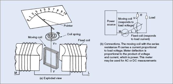
Figure 1 A dynamometer movement
The meter’s second circuit consists of a coil with a series resistance of high value. This is the voltage circuit and produces a magnetic field proportional to the applied voltage.
The direct multiplication of voltage and current values in an AC circuit to obtain a power value can at best be only an approximation. With some electrical components, the voltage and current can be out of step with each. This type of meter construction with its two magnetic fields takes into account any displacement between voltage and current and gives a true power reading.
With AC supplies, the values of voltage and current are continually changing so a true power reading indicates the average power being consumed over a finite period of time, rather than at one instant.
Dynamometer movements find their greatest number of applications in AC work because they integrate both current and voltage values and give a true power reading with a high degree of accuracy. The meter-movement principle is also applied to other types of meters.
While wattmeters can be used on DC, it is not the usual practice. Good voltmeters and ammeters can give quite high accuracy for DC work by multiplying the two meter values together. Figure 1(b) shows how the meters are connected into an AC circuit.
Handheld Wattmeters
Handheld wattmeters are similar in size and shape to a multimeter. Battery powered, they operate electronically and provide a digital readout. Range selection is by a rotary switch. The meter uses RMS values of current and voltage irrespective of the actual waveform and has an accuracy of about 5 per cent of the readout, a Figure which is sufficiently accurate for a portable instrument.
The rotary switch has three sections—voltage, current and power. Maximum ranges are up to about 750 V and 20 A, giving a power range from 400 W to 15 kW. The instrument has the added advantage of being comparatively accurate from 15 Hz to 1 kHz.
Because there are three groups of readings, individual readings of voltage, current and power can be obtained. Some models also indicate the displacement, if any, between voltage and current. The meter may also be referred to as a power analyzer.
Bench-Type Wattmeters
Equipment of the bench type has a far higher degree of accuracy than the portable version and is normally never taken into the field. Expensive to purchase, bench-type wattmeters are kept in a workshop for better protection.
They are usually 240 V mains-powered, but later models are electronically operated. With an analogue readout, the operating frequency is usually from DC (f = 0) to about 15 kHz. Current ranges are up to 10 A with a maximum voltage of 1000 V. This gives a maximum power range from 250 mW to 10 kW.
VA And Var Meters
VA is of course simply the product of V and I, which digital electronics with computerized instrumentation can easily calculate. VAR is calculated using Pythagoras’s theorem, or (VA)2 = P2 + VAR2, i.e. VAR = √(VA2 − P2). The point here is that once P has been measured, VA and VAR are relatively easy to calculate inside the instrument if a microcomputer is used.
Energy Meters (Kwh Meters)
Energy meters are power meters that integrate the power over time. In other words, the energy meter adds the power to increase a value that is stored in memory. Most energy meters are much more complex than that, being able to record a vast amount of data for later harvesting by technicians.
Frequency Meters
Digital electronics are perfect for frequency measurement. Of course the circuit could count the cycles every second and give a readout each second, but they are too fast to do it that way. Digital instruments can actually count the period of the cycle and invert the result to give an answer in hundredths of a hertz, 50 times a second.
High-frequency wattmeters
Wattmeters intended for use on frequencies well above power line frequencies use different principles of operation. Most rely on the heating effect of the current flowing in the circuit. The heat produced generates a voltage proportional to the temperature of a thermocouple. The voltage is then processed and indicated on a meter, whether analogue or digital.
Ultra-high-frequency wattmeters
For frequencies in excess of 300 MHz, parallel-line meters are used. One of the parallel lines has the load current flowing through it and the second line has a voltage induced in it. This voltage is rectified and read against the scale of a meter calibrated for that frequency.
Total Harmonic Distortion Meters
While not something that is typically shown on power meters, total harmonic distortion (THD) can be readily monitored with modern technology to display harmonics, spikes and other issues with power supplies. Harmonics can have disastrous effects within an electrical installation and technicians need to be familiar with the use and operation of THD meters.
Power and Energy Meters Types Key Takeaways
Understanding the wide range of power and energy meters, from traditional mechanical wattmeters to advanced digital instruments like THD meters and high-frequency analyzers, is essential for ensuring accurate measurement and efficient monitoring of electrical systems. These tools are critical in diverse applications—ranging from household energy tracking to industrial power quality assessment—helping engineers and technicians maintain system stability, ensure energy efficiency, and diagnose electrical faults.