This article explores phase control techniques in thyristor power systems, focusing on controlling AC and DC loads through adjustable trigger angles. It discusses the operation, advantages, and disadvantages of half-wave and full-wave controlled rectifiers, emphasizing their applications, waveforms, and performance in varying power requirements.
What is Phase Control Thyristor?
Phase control is the most common technique employed in thyristor power control. Where phase-control techniques are employed, only part of an AC wave is used. The thyristor devices block conduction until they are triggered into the on state.
Triggering of the thyristor may occur at any time in a given half-cycle. The longer triggering is delayed, the lower the load voltage will be.
Use of a thyristor such as an SCR, GTO thyristor or triac with a suitable triggering circuit will allow the load voltage to be varied infinitely from zero to the maximum available value.
The load voltage is in effect controlled by the trigger angle α of the thyristor. The trigger angle is an indication of the amount by which triggering is delayed and is measured in electrical degrees. When the load voltage is at its maximum the trigger angle is zero.
Phase-control techniques may be applied equally well to DC and AC loads supplied from an AC supply. In the case of DC loads the average load voltage is varied, while in the case of AC loads the RMS load voltage is varied. In both cases this results in variations in the average load power.
Figure 1 displays typical load voltage waveforms for a controlled DC load where phase-control techniques are employed.
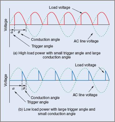
Figure 1 Voltage waveforms for a DC load with phase control
From these waveforms, note that for high load power the trigger angle is small and the conduction angle θ, the period in which the thyristor conducts, is large. For low load power, α is large and θ is small. As the trigger angle increases, the conduction angle decreases. For circuits where the supply is single phase and the load is resistive:
![]()
$$ \alpha +\theta =180^{\circ}$$
$$\textrm{Therefore when } \alpha =45^{\circ},\theta =135^{\circ}$$
Figure 2 shows typical waveforms for a situation where phase-control techniques are employed to control the power in an AC load. The principles are identical to those of the DC application, the only difference being that the load current is bi-directional.
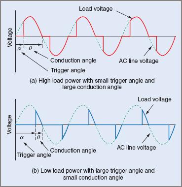
Figure 2 Voltage waveforms for an AC load with phase control
The advantages of phase control are:
- A wide range of applications, from very low to very high power loads
- High efficiency
- Small size, compact equipment
- Moderate cost.
Phase control has two major disadvantages:
- The ‘chopped’ waveform produces harmonics (multiples of the supply frequency) that reflect back into the supply system. These harmonics may in extreme cases interfere with other equipment.
- The rapid switching of the thyristors causes the load current to rise very quickly, producing high-frequency oscillations. The frequency of these oscillations is normally in the AM broadcast band and can cause interference to communications equipment operating at those frequencies. The oscillations, called radio frequency interference (RFI), can radiate directly but can also penetrate the supply system. The RFI generated by thyristor circuits increases as the trigger angle approaches 90°. It is at a minimum when triggering occurs at 0° or 180°. The RFI may be prevented from getting back into the supply system by the use of RFI suppression circuits as shown in Figure 3.
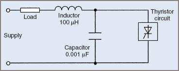
Figure 3 RFI suppression circuit diagram
At radio frequencies, the capacitor provides a low impedance path for RFI generated by the thyristor to return to the thyristor. For power line frequencies the capacitor has a high impedance and has no effect on the operation of electrical equipment.
The inductor offers a high impedance path to high frequency oscillations attempting to enter the supply. At power line frequencies it offers minimal impedance and does not affect the operation of the electrical equipment.
Half-Wave Controlled Rectifier—Single Phase
The function of this circuit is to control the average value of power in a DC load supplied from an AC source. This is achieved by controlling the average value of load voltage using phase-control techniques.
The circuit configuration is similar to the single-phase half-wave rectifier, the major change being that the diode is replaced by an SCR. A trigger circuit must also be included to control the SCR. Many variations of the trigger circuit are possible. Only one trigger circuit will be discussed.
In a circuit of this type it is necessary to configure the trigger circuit so that the trigger pulses may be varied from the commencement of the positive half-cycle through to the end of the half-cycle. The pulses must be synchronized with the mains so that for a given setting on RV1 the trigger delay is the same in every positive half-cycle.
In the circuit in Figure 4, D1, R1 and ZD1 provide a regulated supply for the UJT trigger circuit. The trigger circuit is connected such that when the SCR is triggered on, the trigger circuit is effectively short-circuited, owing to the very low forward voltage drop across a conducting SCR. This results in:
- Only one trigger pulse in each positive half-cycle
- The time taken for the capacitor to reach the peak point voltage and hence cause the UJT to trigger the SCR being the same in each positive half-cycle.
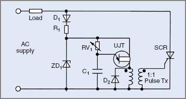
Figure 4 Single-phase half-wave controlled rectifier circuit configuration
As the time taken for the capacitor voltage to rise to the peak point voltage of the UJT increases, the triggering of the SCR is delayed further into each positive half-cycle, causing the average load voltage to be reduced. The trigger angle is controlled by the setting on RV1. As RV1 is increased, the time constant in the trigger circuit increases, increasing the trigger angle. Similarly, if the setting on RV1 is reduced, the time constant and trigger angle decrease.
When RV1 is at its minimum value, the trigger angle will be zero and the load voltage will be at its maximum value.

$$V_{L}=0.45V_{AC}$$
$$\textrm{where }V_{L}=\textrm{average load voltage in volts}$$
$$V_{AC}=\textrm{AC input voltage}$$
This value is identical to that obtained from an uncontrolled single-phase half-wave rectifier.
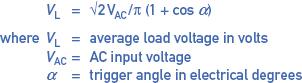
When RV1 is set to its maximum value, the trigger angle will be 180° and the load voltage will be zero. For trigger angles between 0° and 180°, the load voltage is determined from:
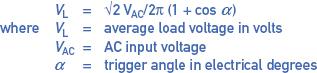
$$V_{L}=\sqrt{2V_{AC}/2\pi \left ( 1+cos\alpha \right )}$$
$$\textrm{where V}_{L}=\textrm{average load voltage in volts}$$
$$V_{AC}=\textrm{AC input voltage}$$
$$\alpha = \textrm{trigger angle in electrical degrees}$$
DC Load Voltage Calculation Example 1
Determine the DC load voltage supplied from a single-phase half-wave controlled rectifier where the AC input voltage is 240 V and the trigger angle is set to 60°.
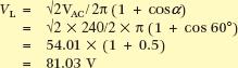
$$V_{L}=\sqrt{2V_{AC}/2\pi \left ( 1+cos\alpha \right )}=\sqrt{2\times 240/2\times \pi \left ( 1+cos60^{\circ} \right )}=54.01\times \left ( 1+0.5 \right )=81.03V$$
The peak reverse voltage to which the SCR is subjected is also important and is found from:
$$PRV=\sqrt{2V_{AC}}$$
SCR Peak Reverse Voltage Calculation Example 2
In Example 1 the AC input voltage was 240 V. Determine the required PRV rating of the SCR.
![]()
$$PRV=\sqrt{2V_{AC}}=\sqrt{2\times 240}=339.4V$$
The controlled single-phase half-wave rectifier has disadvantages similar to those of the uncontrolled single-phase half-wave rectifier. The most significant are:
- Low DC output for a given AC input
- Low ripple frequency and ‘coarse’ load voltage wave-form
- Saturation of the core of the supply transformer where the load current is high.
Half-Wave Controlled Rectifier Waveforms
Figure 5 shows typical waveforms for the circuit in Figure 4 when the trigger angle is set to 60°.
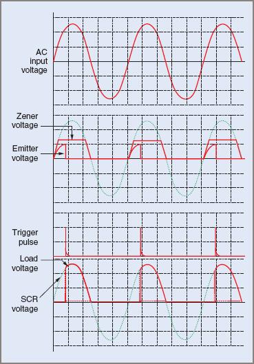
Figure 5 Single-phase half-wave controlled rectifier waveforms
Owing to the nature of the load voltage waveform and other disadvantages, the single-phase half-wave controlled rectifier finds few applications in industry. By contrast, polyphase half-wave controlled rectifiers are used extensively.
Full-Wave Controlled Rectifier—Single Phase
This rectifier circuit overcomes the major disadvantages of the half-wave controlled rectifier. The only way in which further improvements in performance may be obtained is to utilize polyphase rectifiers.
The single-phase full-wave controlled rectifier takes the form of a bridge rectifier, however, it might take one of the following forms:
- Two SCRs and two diodes—a half-controlled bridge
- Four SCRs—a fully controlled bridge.
Only the half-controlled bridge will be discussed here because a fully controlled bridge offers no advantages when supplying resistive loads, yet requires a more complex trigger circuit. Fully controlled bridges are used in applications such as DC motor speed control where regenerative braking is required.
Half-Controlled Bridge Rectifier
A half-controlled bridge is shown in Figure 6.
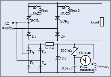
Figure 6 Single-phase half-controlled bridge rectifier Circuit Configuration
In this circuit, load current in one half-cycle is supplied via SCR1 and D2 with SCR2 and D1 being reverse biased. In the next half-cycle, load current is supplied via SCR2 and D1 with SCR1 and D2 reverse biased. Load current cannot flow of course until the appropriate SCR is triggered into the on state.
The SCRs and diodes in this circuit operate on a 50 per cent duty cycle; that is, they conduct for only 50 per cent of the time. This fact may be taken into account, with some degree of caution, when selecting the current rating for the SCRs and diodes for a particular application.
The manner in which the trigger circuit is configured in this circuit is such that each SCR will receive multiple trigger pulses in each half-cycle. This does not normally present a problem, however, because a trigger pulse has no effect on a conducting SCR, or on an SCR that is reverse biased.
Like the half-wave controlled rectifier, the output voltage from this circuit is controlled by the potentiometer in the trigger circuit.
When α = 0° the load voltage is a maximum, and:

$$V_{L}=0.9V_{AC}$$
$$\textrm{where V}_{L}=\textrm{average load voltage in volts}$$
$$V_{AC} =\textrm{AC input voltage}$$
When α = 180°, the load voltage is zero. For trigger angles between 0° and 180° the load voltage may be determined from the following expression:
$$V_{L}=\sqrt{2V_{AC}/2\pi \left ( 1+cos\alpha \right )}$$
$$\textrm{where V}_{L}=\textrm{average load voltage in volts}$$
$$V_{AC}=\textrm{AC input voltage}$$
$$\alpha = \textrm{trigger angle in electrical degrees}$$
DC Load Voltage Calculation Example 3
Determine the DC load voltage supplied from a single-phase half-controlled bridge rectifier where the AC input voltage is 240 V and the trigger angle is set to 60°.
![]()
$$V_{L}=\sqrt{2V_{AC}/\pi \left ( 1+cos\alpha \right )}=\sqrt{2\times 240/\pi \left ( 1+0.5 \right )}=162.05V$$
The SCRs and diodes in this circuit are subjected to the same PRV as the diodes in a single-phase uncontrolled bridge rectifier, that is:
$$PRV=\sqrt{2V_{AC}}$$
SCR Peak Reverse Voltage Calculation Example 4
In the circuit in Figure 6 the AC input voltage is 240 V. Determine the required PRV rating of the SCRs and diodes.
![]()
$$PRV=\sqrt{2V_{AC}}=\sqrt{2\times 240}=339.4V$$
Note that the output voltage for this circuit is double that of the half-wave controlled rectifier for the same trigger angle. The controlled bridge rectifier is better suited to, and is commonly used to supply, low- to medium-power loads.
The circuit in Figure 6 can be modified to configure the trigger circuit so that only one trigger pulse is supplied in each half-cycle as in Figure 7. Both SCRs are still triggered simultaneously; however, only the SCR that is forward biased will turn on.
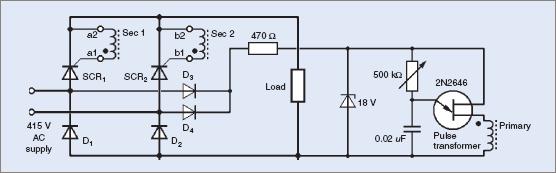
Figure 7 Single-phase half-controlled bridge rectifier with modified trigger circuit
Single-Phase Half-Controlled Bridge Rectifier Waveforms
Typical waveforms for a single-phase half-controlled bridge rectifier circuit, where the trigger angle is set at 60°, are shown in Figure 8.
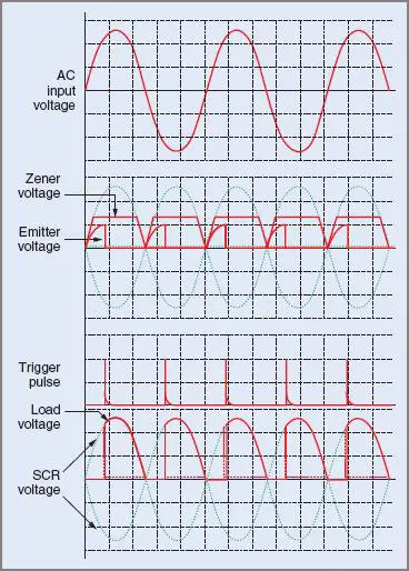
Figure 8 Single-phase half-controlled bridge waveforms
Comparing these waveforms, particularly the load voltage waveform, with those of Figure 5, it can be seen that better use is made of the supply waveform. Since both half-cycles of the supply are utilized, the problem of the supply transformer saturating at high load currents is overcome.
Also, since the periods between load voltage pulses are shorter (double the ripple frequency) the load power is smoother. This is particularly evident where the load is the armature of a DC motor, where the torque may be pulsating if the rectifier output is similar to the half-wave rectifier circuit.
SCR Thyristor Phase Control Key Takeaways
Phase control techniques in thyristor-based power systems are essential due to their versatility and efficiency in regulating power delivery to both AC and DC loads. These methods allow precise control of output voltage and current through the manipulation of the trigger angle, enabling a wide range of applications—from lighting dimmers and heating control to motor speed regulation and industrial automation. By selecting appropriate rectifier configurations—such as half-wave or full-wave controlled rectifiers—engineers can optimize performance for specific load requirements while balancing cost, size, and complexity. Despite certain disadvantages like harmonic distortion and radio frequency interference, the ability to finely tune power levels makes phase-controlled thyristors indispensable in modern electrical and electronic systems, especially where energy efficiency and compact design are priorities.