The article outlines various types of induction motor starter circuits, including Direct-On-Line, Star–Delta, Primary Resistance, Autotransformer, and Secondary Resistance starters. It explains their basic operation principles and how each type manages motor starting and voltage control using contactor circuits.
The following are push-button motor starter circuits for the more common types of starters. It must be emphasized that the circuits presented are only representative. There are many variations for each type and further variations from one manufacturer to another.
These circuits present the principles of operation only and it is to be expected that other starters encountered might have different circuits.
Direct-On-Line Contactor Starter Circuit

Figure 1 Contactor circuit Diagram for DOL starting
Circuit operation
1. Pressing the start button completes a circuit from L3 through the normally closed stop button to coil K1/4 and the overload to L2.
2. Main contactor coil K1/4 then closes and applies full line voltage directly to the motor via contactor contacts K1.1, K1.2 and K1.3.
3. Contact K1.4 bridges out the start button contacts so that on the release of the start button the contactor remains in the operational state. That is, the control circuit is latched in the ‘on’ position. Pressing the stop button disables the latching circuit and allows the main contactor to revert to the ‘off’ state.
Star–Delta Contactor Starter Circuit

Figure 2 Contactor circuit Diagram for star–delta starting
Circuit Operation
1. Pressing the start button completes a circuit from L3 through the normally closed stop button and two normally closed contactor contacts (K4.1 and K3.4) to coil K2/5 and the overload contact to L2.
2. When K2/5 operates, it causes the ends of the three windings to be joined in star configuration via contacts K2.1, K2.2 and K2.3.
3. Simultaneously, coil K3/5 is open-circuited by K2.5. This is the delta-connecting coil and it must be isolated when the star connection is in operation. Similarly, when the delta connection is in operation, the star connection must be isolated, using a method called ‘electrical interlocking’. As a precaution, the star and delta connecting contactors are often mechanically interlocked, in addition to the electrical interlocking provided by contacts K2.5 and K3.4.
4. When K2.4 closes, a voltage is applied to the timer K4/1 and to coil K1/4. This allows K1.4 to close and bridge the start button.
5. Contacts K1.1, K1.2 and K1.3 close and apply a voltage to the ‘starts’ of the motor windings.
6. The voltage applied across the windings at this time is only a proportion of full line voltage (58%), and the starting current is reduced accordingly.
7. When the time delay period has elapsed, contact K4.1 opens and forces contactor K2/5 to disconnect the star connection. The dropping-out action of K2/5 causes contact K2.5 to close and energize coil K3/5. This action open-circuits the interlocking contact K3.4 and also switches off the timer K4/1 via K3.5.
8. Contacts K3.1, K3.2 and K3.3 close and complete the delta connection, allowing full line voltage to be applied to the motor.
9. Pressing the stop button de-energizes all coils and allows the starter to revert to the ‘off’ state.
Primary Resistance Contactor Starter Circuit
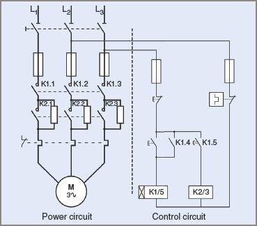
Figure 3 Contactor circuit Diagram for primary resistance starting
Circuit Operation
1. Pressing the start button completes a circuit from L3 through the normally closed stop button to coil K1/5 and the overload to L2.
2. The main contactor K1/5 operates. Contact K1.4 closes and bridges out the start button contacts, so that on release of the start button the K1/5 contactor circuit remains latched.
3. Contacts K1.1, K1.2 and K1.3 close, and a reduced line voltage is applied to the motor through the resistors in series with each line to the motor. The starting current is limited by the resistors to a value below that of DOL starting.
4. Delayed-action contact K1.5 operates after a predetermined delay and completes the circuit for coil K2/3. Its operation causes contacts K2.1, K2.2 and K2.3 to close and allow full line voltage to be applied to the motor.
5. Pressing the stop button de-energizes all coils and allows the starter to revert to the ‘off’ state.
Autotransformer Contactor Starter Circuit
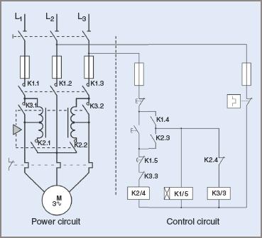
Figure 4 Contactor circuit Diagram for autotransformer starting
Circuit Operation
1. Pressing the start button completes a circuit from L3 through the normally closed stop button, a normally closed delay contact K1.5, electrical interlock K3.3, coil K2/4, and the normally closed thermal overload contact to L2.
2. When K2/4 is activated, it closes the contacts K2.1 and K2.2 connecting the ends of the autotransformers to line L2 in an open-delta configuration.
3. The operation of K2/4 simultaneously closes contact K2.3 and opens contact K2.4, the electrical interlock, to prevent K3/3 operating while K2/4 is active.
4. K2.3 supplies power to coil K1/5, which is also activated. Contacts K1.1, K1.2, K1.3 and K1.4 close. Full line voltage is connected to the autotransformers and a reduced line voltage is supplied to the motor via the transformer tapping. Contact K1.4 ensures that a voltage is available to the control circuit when the start button is released.
5. The delayed opening contact K1.5 opens after a predetermined time lapse, de-energizing K2/4 and open-circuiting the delta connection. Contact K2.4 then closes again and coil K3/3 is activated.
6. Contacts K3.1 and K3.2 close, and full line voltage is applied to the motor through the K1/5 contacts in series with two lines. The electrical interlock contact K3.3 opens and isolates coil K2/4.
7. Pressing the stop button de-energizes all coils and allows the starter to revert to the ‘off’ state.
Secondary Resistance Contactor Starter Circuit
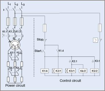
Figure 5 Contactor circuit Diagram for secondary resistor starting
Circuit Operation
1. Pressing the start button completes a circuit from L3 through the normally closed stop button, coil K1/4, and the thermal overload contact to L2. Coil K2/1, which is in parallel with coil K1/4, is activated at the same time as K2/1 but only operates after a predetermined time delay.
2. Contact K1.4 bridges out the start button contacts so that on the release of the start button the contactor remains in the operational state, that is, the control circuit is latched in the ‘on’ position.
3. Contacts K1.1, K1.2 and K1.3 close and apply full line voltage to the stator terminals of the motor. The rotor has two resistors in series with each winding and, because the ends are connected in star configuration, current flows in the rotor windings and the motor is able to generate torque and commence turning.
4. After the delay time, K2/1 operates and closes contact K2.1. This causes K4/2 to be energized, along with K3/1, a second time-delay relay.
5. Contacts K4.1 and K4.2 then close and reduce the amount of resistance connected across the slip-rings. This action enables the motor to attain a higher speed.
6. After a further time delay, coil K3/1 operates and closes contact K3.1. Coil K5/2 is then activated and closes contacts K5.1 and K5.2. This action removes the remainder of the resistance in the rotor circuit and the motor is in its normal running mode.
7. Pressing the stop button de-energizes all coils and allows the starter to revert to the ‘off’ state.
Induction Motor Starter Key Takeaways
Understanding various types of induction motor starter circuits is crucial for optimizing motor performance and protecting electrical systems. Each induction motor starter—whether it’s Direct-On-Line, Star–Delta, Primary Resistance, Autotransformer, or Secondary Resistance—serves a specific purpose based on motor size, application, and required starting conditions. For instance, large industrial machines benefit from the reduced inrush current offered by star–delta and autotransformer configurations, while smaller motors can rely on the simplicity of the DOL method. The induction motor starter plays a key role in ensuring smooth operation, reducing mechanical stress, and improving energy efficiency. With widespread use in sectors such as manufacturing, water treatment, and HVAC,